Chapters
Table of Contents

Related Manuals for Gotting HG G-98830YA


Summary of Contents for Gotting HG G-98830YA
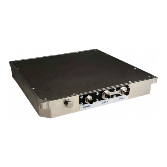
- Page 1 Transponder Transponder Antenna HG G-98830YA 2-dimensional Position Detection & Identification Outdoor, flat Design English, Revision 02 Date: 21.06.2021 Dev. by: WM Author(s): RAD / AF Innovation through Guidance www.goetting-agv.com...
- Page 2 Programming of Transponders © 2021 Götting KG, errors and modifications reserved. The Götting KG in D-31275 Lehrte has a certified quality management system according to ISO 9001. Operating Manual HG G-98830YA | English, Revision 02 | Date: 21.06.2021...
-
Page 3: Table Of Contents
Mounting the Antenna on the Vehicle ..............28 7.3.7 Antenna Switch-On ....................... 30 Commissioning ................31 Connecting the Antenna to a Computer ..............31 Configuring the Terminal Program................32 Operating Manual HG G-98830YA | English, Revision 02 | Date: 21.06.2021... - Page 4 Updating the Software ......................74 Maintenance ..................76 Disposal ................... 77 Troubleshooting ................78 14.1 Error table..........................78 14.2 Reducing Interferences .....................79 14.2.1 Which Interfering Influences are There?..............79 14.2.2 What happens when Crossing a Transponder?.............79 Operating Manual HG G-98830YA | English, Revision 02 | Date: 21.06.2021...
- Page 5 List of Tables ................. 103 Index ....................105 Copyright and Terms of Liability ..........108 20.1 Copyright ..........................108 20.2 Exclusion of Liability ....................... 108 20.3 Trade Marks and Company Names ................108 Operating Manual HG G-98830YA | English, Revision 02 | Date: 21.06.2021...
-
Page 6: About This Operating Manual
The following links refer to specific product pages. – Disc transponder HW DEV00095/00098 http://www.goetting-agv.com/components/00095 – Rod transponder HG G-71325XA http://www.goetting-agv.com/components/71325 – Transponder programming device HG G-81840 http://www.goetting-agv.com/components/81840 – Navigation controller HG G-73650 (optional) http://www.goetting-agv.com/components/73650 Operating Manual HG G-98830YA | English, Revision 02 | Date: 21.06.2021... -
Page 7: Declaration Of Conformity
The paragraph describes the consequences of not heeding the warning. danger prevention The paragraphs for explain, how to avoid the danger. Operating Manual HG G-98830YA | English, Revision 02 | Date: 21.06.2021... -
Page 8: Symbols
Whenever the pressing of letter keys is required for program entries, the required etter eys are indicated as such (for any programs of Götting KG small and capital letters are equally working). Operating Manual HG G-98830YA | English, Revision 02 | Date: 21.06.2021... -
Page 9: Definitions
–X (usually direction of Active area for posi- travel) tion detection Crossing the Y-axis during movement in direction +X or -X triggers PosiPuls, see section 9.1 on page 35 Operating Manual HG G-98830YA | English, Revision 02 | Date: 21.06.2021... -
Page 10: Abbreviations
CANopen® Controller Area Network open Electronic Data Sheet Automated Guided Vehicle Process Data Object RFID Radio-Frequency Identification Service Data Object Programmable Logic Controller or PC that performs control functions Operating Manual HG G-98830YA | English, Revision 02 | Date: 21.06.2021... -
Page 11: Safety Instructions
The field of application of the transponder antenna HG G-98830YA is the position detection of Automated Guided Vehicles (AGV). The transponder antenna HG G-98830YA may only be used by qualified personnel at the place of installation (e.g. -
Page 12: User Qualification
2.4 General Safety Instructions Ensure that the transponder antenna HG G-98830YA is used only in applica- tions, – where sufficient measures for personal protection and safe detection of obstacles are implemented, –... -
Page 13: Obligations Of The Operator
The operator must not modify or alter the transponder antenna without authoriza- tion. Otherwise, the operating permit will become invalid. Operating Manual HG G-98830YA | English, Revision 02 | Date: 21.06.2021... -
Page 14: Scope Of Delivery
M12 plug 5-pin, A-coded HW DEV00095 Disc transponder Usually mounting on the roadway HW DEV00098 Disc transponder pre-programmed Usually mounting on the roadway HG G-71325XA Rod transponder Usually mounting in the ground Operating Manual HG G-98830YA | English, Revision 02 | Date: 21.06.2021... -
Page 15: Optional Accessories
HG G-73650ZD Navigation controller for calculating the courses of the vehicle Operating Manual HG G-98830YA | English, Revision 02 | Date: 21.06.2021... -
Page 16: Device Overview
Transponders with trovan® coding are used as reference marks for the track guid- ance (see 3.1 „Required Accessories“ on page 14). Further documents can be ob- tained from our Internet server (see 1.1.2 „Additional Applicable Documents“ on page 6). Operating Manual HG G-98830YA | English, Revision 02 | Date: 21.06.2021... -
Page 17: Structure Of The Transponder Code
Device Overview – Chapter 4 4.2.2 Structure of the Transponder Code The antenna HG G-98830YA evaluates only the data block 2 with its 20 useful bits. The data protection is carried out for the transponders via row (for 3 bits each) and column parities. -
Page 18: Operating Principle
Fur- thermore, there are other systems for transmitting and decoding the code which are not described in this operating manual. Operating Manual HG G-98830YA | English, Revision 02 | Date: 21.06.2021... -
Page 19: Track Guidance With Transponders
The downstream navigation system or the navigation controller (neither of which is part of the transponder antenna) resets its estimated position at these points to the precisely determined value. Operating Manual HG G-98830YA | English, Revision 02 | Date: 21.06.2021... -
Page 20: Position Detection With A Navigation Controller
GPS signals for position detection. It also manages courses and converts the posi- tions of the sensors mounted on the vehicle into the coordinate system of the facility. Operating Manual HG G-98830YA | English, Revision 02 | Date: 21.06.2021... - Page 21 Information on the navigation controller can be found at: http://www.goetting-agv.com/components/73650 Operating Manual HG G-98830YA | English, Revision 02 | Date: 21.06.2021...
-
Page 22: Storage
Store the device in closed rooms only. Make sure that the storage room is sufficiently ventilated and dry. Protect the device from damage caused by dirt, dust or moisture. Operating Manual HG G-98830YA | English, Revision 02 | Date: 21.06.2021... -
Page 23: Mounting
1.1.2 „Additional Applicable Documents“ on page 6). A minimum distance of 500 mm is required between two transponders. Mount the transponders as horizontally (HW DEV00095/HW DEV00098) or vertically (HG G-71325) as possible. Operating Manual HG G-98830YA | English, Revision 02 | Date: 21.06.2021... -
Page 24: Preparation Of Connection Cables
Damage to CAN bus devices If voltage is applied to pin 4 or 5, other devices connected to the CAN bus may be damaged. Never connect voltage to pin 4 or 5. Operating Manual HG G-98830YA | English, Revision 02 | Date: 21.06.2021... -
Page 25: Mounting The Transponder Antenna
7.3 Mounting the Transponder Antenna 7.3.1 Operating Conditions of the Antenna The transponder antenna HG G-98830YA is approved for indoor and outdoor use. It may be used in a temperature range from 0 to +50° C. The relative humidity at 25° C may be max. -
Page 26: Minimum Distance Between Identical Transponder Antennas
Two or more transponder antennas operating at the frequencies 128/64 kHz must maintain a minimum distance from each other in order not to interfere with each other. The minimum distance between two HG G-98830YA transponder antennas is 200 mm. As a matter of principle, larger transponder antennas must maintain a greater dis- tance. -
Page 27: Connection Example
Voltage supply 18 - 36 V alternatively RS 232 – alternatively RS 232 as data or service interface Transponder antenna POWER CAN 1 CAN 2 Ground Transponder (on or within the ground Operating Manual HG G-98830YA | English, Revision 02 | Date: 21.06.2021... -
Page 28: Mounting The Antenna On The Vehicle
Position of the mounting holes and dowel pin cut-outs Figure 14 M5 resp. M6 (4x, s. below) Dowel pin cut-outs (8 x) Mounting side with position of the mounting holes Operating Manual HG G-98830YA | English, Revision 02 | Date: 21.06.2021... -
Page 29: Figure 15 Specifications For Dowel Pins On The Vehicle Floor
Screw DIN933 M5xL A4 (on all 4 corners of the housing) Nut DIN985 M5 Vehicle floor self-locking A4 Thread hole Length approx. 15 mm Washer DIN125-A 5,3x10x1 A4 Antenna Operating Manual HG G-98830YA | English, Revision 02 | Date: 21.06.2021... -
Page 30: Antenna Switch-On
After this time, the actual antenna program starts. If you have configured the Auto- Tune function (see Figure 27 on page 61), an automatic adjustment of the transmit- ting coil is now performed. This process takes another 16 seconds. Operating Manual HG G-98830YA | English, Revision 02 | Date: 21.06.2021... -
Page 31: Commissioning
Commissioning WARNING Danger due to lack of safety measures The transponder antenna HG G-98830YA does not contain any safety devices. Only use this antenna in applications where sufficient measures for personal protection and safe detection of obstacles have been implemented. -
Page 32: Configuring The Terminal Program
In the Connect via sub item, select Direct connection via the corresponding port and confirm with o.k. Exit HyperTerminal. You will be prompted to save. Save the changed values. COM1 The port is now set. Operating Manual HG G-98830YA | English, Revision 02 | Date: 21.06.2021... -
Page 33: Configuring The Antenna (Monitor Program)
You must restart the system for the changes to become active. Disconnect the antenna from the operating voltage for a short time and reconnect it. The transponder antenna is now properly commissioned. Operating Manual HG G-98830YA | English, Revision 02 | Date: 21.06.2021... - Page 34 Chapter 8 – Commissioning If you need a reference file for later settings: Archive the file (see 10.2.17 „P(r)int Parameters“ on page 73). Operating Manual HG G-98830YA | English, Revision 02 | Date: 21.06.2021...
-
Page 35: Interfaces
In the state as delivered, the serial interface is in Monitor only mode. You can then use the serial interface via a computer as a service interface for configuration. Operating Manual HG G-98830YA | English, Revision 02 | Date: 21.06.2021... -
Page 36: List Of System Values That Can Be Output
(e.g. 245 corresponds to 24.5 V) 1 Byte 0x0000.0080 unsigned char Current consumption in [10 mA] resolution (e.g. 100 corresponds to 1000 mA) 1 Byte 0x0000.0100 unsigned char Temperature measured in the antenna [°C] Operating Manual HG G-98830YA | English, Revision 02 | Date: 21.06.2021... -
Page 37: Table 9 Possible System States
±10 mm is determined and this bit is set. 0x4000 0x8000 *) These bits are deleted after the transponder leaves the antenna field. Operating Manual HG G-98830YA | English, Revision 02 | Date: 21.06.2021... -
Page 38: List Of System Commands
Set tuning value to 1 ASCII transparent HEX ASCII = 3964R Set tuning value to 2 ASCII transparent HEX ASCII = 3964R Set tuning value to 3 ASCII transparent HEX ASCII = Operating Manual HG G-98830YA | English, Revision 02 | Date: 21.06.2021... - Page 39 Set tuning value to 10 ASCII transparent HEX ASCII = 3964R Set tuning value to 11 ASCII transparent HEX ASCII = 3964R Set tuning value to 12 ASCII transparent HEX ASCII = Operating Manual HG G-98830YA | English, Revision 02 | Date: 21.06.2021...
- Page 40 Code in the Transmission of the least format tt significant 16 bits of the For code „1234“ transponder code to be e.g. 12 programmed. ASCII transparent HEX ASCII = Operating Manual HG G-98830YA | English, Revision 02 | Date: 21.06.2021...
-
Page 41: Can Bus
CANopen® master – CAN-Identifier The address on which a PDO, SDO is sent – Node ID For CANopen® the address of the device, which is added to the CAN identifier Operating Manual HG G-98830YA | English, Revision 02 | Date: 21.06.2021... -
Page 42: Operating Modes And States
Full configuration possible, set PDOs are sent Note that a CAN identifier or, in the case of CANopen®, the combination of CAN identifier and node identifier must always be unique! Operating Manual HG G-98830YA | English, Revision 02 | Date: 21.06.2021... -
Page 43: Can
1 Byte unsigned char Operating current (see telegram description in Table 8 on page 36) 1 Byte signed char Operating temperature (see telegram description in Table 8 on page 36) Operating Manual HG G-98830YA | English, Revision 02 | Date: 21.06.2021... -
Page 44: Can Message Object - P-Identifier, Send Object
(see 10.2.9 „CA(N)-Open-Parameters“ on page 65). The mea- sured values of the system are transmitted via so-called TxPDOs. SDOs are used to set parameters. The CAN identifiers are derived from the node address (1 ... 127). Operating Manual HG G-98830YA | English, Revision 02 | Date: 21.06.2021... -
Page 45: Description Of The Process Data Objects (Pdo)
0 … ffff.ffff 20 Bit transponder-Code (R/W Tran- sponder) Devia- signed 16 0xff83 … 0x007d X-deviations, ±125 tion In case of invalid values (z. B. no transponder found) = 32767 Operating Manual HG G-98830YA | English, Revision 02 | Date: 21.06.2021... -
Page 46: Heartbeat
The identifi- ers for read and write access are: Identifier for read and write access Table 25 Access mode Identifier Read access 0x600 + Node-Address Write access 0x580 + Node-Address Operating Manual HG G-98830YA | English, Revision 02 | Date: 21.06.2021... -
Page 47: Object Directory
All objects relevant for the device are entered in the CANopen® object dictionary. The complete object directory is listed in section 16.4 „Overview of the CANopen® Directory“ on page 89. Operating Manual HG G-98830YA | English, Revision 02 | Date: 21.06.2021... -
Page 48: Configuration Of The System Via The Service Interface
HyperTerminal configuration files) to start the monitor program. You can download the configuration files in the latest version from our Internet serv- er at any time: http://www.goetting-agv.com/components/transponderconf Start the monitor program on the PC. Operating Manual HG G-98830YA | English, Revision 02 | Date: 21.06.2021... -
Page 49: Figure 22 Send File In Monitor Program
The menus then appear directly in the HyperTerminal window. You will first see the main menu from Figure 23 on page 50. If the monitor program does not start: Check the following points: Operating Manual HG G-98830YA | English, Revision 02 | Date: 21.06.2021... -
Page 50: Using The Monitor Program
The item (Q)uit Monitor will only appear if the serial interface is set to a procedure other than Monitor only. In this case, quit the monitor program with , so that the serial interface switches back to the configured 3964R or transparent output. Operating Manual HG G-98830YA | English, Revision 02 | Date: 21.06.2021... -
Page 51: Display Of System Variables And Status Messages
This mechanism is used to check whether a transponder or a foreign signal is present. If this counter exceeds an adjustable value (see 10.2.6 „(T)ime & Code“ on page 56), then the RX_NOISE bit is set in the system status. Operating Manual HG G-98830YA | English, Revision 02 | Date: 21.06.2021... -
Page 52: Activate Sub Menus
Changes in the (S)erial Output menu item only take effect after you have perma- nently saved them (see 10.2.14 „(L)oad values to EEProm“ on page 71) and briefly disconnected the antenna from the supply voltage (system reset). Depending on the Operating Manual HG G-98830YA | English, Revision 02 | Date: 21.06.2021... -
Page 53: Figure 24 Menu: (S)Erial Output
Selection: Monitor only (Service/Configuration) 3964R (Data) transparent (Data) For setting the procedure for the data transmission: Press the key and enter the desired value. Operating Manual HG G-98830YA | English, Revision 02 | Date: 21.06.2021... - Page 54 (see Figure 25). In the example the mask has the value 0x1fff and the telegram length is 23. Selection: none, display function only To display the generated telegram: Press the key The following screen appears: Operating Manual HG G-98830YA | English, Revision 02 | Date: 21.06.2021...
-
Page 55: Figure 25 Output At (D)Isplay Telegram Content
Selection: 0 = Output only occurs when a transponder is decoded in the field 1 = The output is permanent according to the set (S)erial Data Period Operating Manual HG G-98830YA | English, Revision 02 | Date: 21.06.2021... -
Page 56: T)Ime & Code
In the (T)ime & Code menu, you set the values for the transponder decoding, the po- sition calculation and the positioning pulse. To switch from the main menu to the menu (T)ime & Code: Press the key The following menu is shown: Operating Manual HG G-98830YA | English, Revision 02 | Date: 21.06.2021... -
Page 57: Figure 26 Menu: (T)Ime & Code
P = The positioning channel D for minimization of interferences is selected. To select the reception channel for code transmission: Press the key and enter the desired value. Operating Manual HG G-98830YA | English, Revision 02 | Date: 21.06.2021... - Page 58 0 = The positioning pulse can be output independently of the code reading on center crossing. Positioning pulses can also be output if interference is present. 1 = The positioning pulse will is only enabled after decoding a transponder. Operating Manual HG G-98830YA | English, Revision 02 | Date: 21.06.2021...
- Page 59 time set with or after the voltage S drops below the threshold set with Operating Manual HG G-98830YA | English, Revision 02 | Date: 21.06.2021...
-
Page 60: F)Requency & Antenna Tuning
Use the (F)requency & Antenna Tuning menu to enter the frequency for the antenna and tune it. To switch from the main menu to the menu (F)requency & Antenna Tuning: Press the key The following menu is shown: Operating Manual HG G-98830YA | English, Revision 02 | Date: 21.06.2021... -
Page 61: Figure 27 Menu: (F)Requency & Antenna Tuning
Selection: 0 = Auto tuning is deactivated. 1 = Auto tuning is activated. To set auto tuning: Press the key and enter the desired value. Operating Manual HG G-98830YA | English, Revision 02 | Date: 21.06.2021... -
Page 62: Basic C(A)N-Parameters
Tseg(2) [1..7]: 2 sp: 80 % (P)eriod [4.500mS]: Co(n)tinous Telegrams CAN on Re(m)ote Request (F)reeze Values for n Telegrams [0..20]: (O)rder of Data Transfer (0= HiByte first): (Q)uit Menue Operating Manual HG G-98830YA | English, Revision 02 | Date: 21.06.2021... - Page 63 By entering 0, the particular message object will be deactivated. To enter the CAN addresses for the Message Objects: Press the keys and enter the respective CAN address. Operating Manual HG G-98830YA | English, Revision 02 | Date: 21.06.2021...
- Page 64 1 = The output is permanent. To select this function: Press the key To switch off this function again: Press the key again. Operating Manual HG G-98830YA | English, Revision 02 | Date: 21.06.2021...
-
Page 65: Ca(N)-Open-Parameters
Use the menu CA(N)-Open-Parameters to adjust the different parameters for the CANopen®. To switch from the main menu to the menu CA(N)Open-Parameters: Press the key The following menu is shown: Operating Manual HG G-98830YA | English, Revision 02 | Date: 21.06.2021... -
Page 66: Figure 30 Menu: Ca(N)-Open-Parameters
With the parameter (N)ode ID you can set the node address. Value range: 1 … 127 To select the node address: Press the key and enter the desired value. Operating Manual HG G-98830YA | English, Revision 02 | Date: 21.06.2021... - Page 67 Value range: 8 … 32000 ms To specify the inhibit time of the PDO transmission: Press the keys and enter the desired value. Operating Manual HG G-98830YA | English, Revision 02 | Date: 21.06.2021...
- Page 68 0 = HiByte first 1 = LowByte first To set the byte order: Press the key and enter the desired value. Operating Manual HG G-98830YA | English, Revision 02 | Date: 21.06.2021...
-
Page 69: D)Isplay Systemstatus
A telegram counter The output is at 38.400 Baud, 8 Bit and even parity. To switch from the main menu to the menu Cs(v): Press the key Operating Manual HG G-98830YA | English, Revision 02 | Date: 21.06.2021... -
Page 70: Y) Display Histogram
X and Y directions. To switch from the main menu to the menu (Y) display Histogram: Press the key The following menu is shown: Operating Manual HG G-98830YA | English, Revision 02 | Date: 21.06.2021... -
Page 71: W)Rite Transponder
With the menu (L)oad values to EEProm you store the parameters in the non-volatile memory. To switch from the main menu to the menu (L)oad values to EEProm menu: Press the key Operating Manual HG G-98830YA | English, Revision 02 | Date: 21.06.2021... -
Page 72: U)Pdate Firmware
All values changed by the user can be saved and restored from a host PC. The XMO- DEM protocol is used for file transfer: To import a data set from the host to the antenna: Press the key Operating Manual HG G-98830YA | English, Revision 02 | Date: 21.06.2021... -
Page 73: P(R)Int Parameters
Press any key. The values are output and saved by HyperTerminal. Terminate the recording in HyperTerminal in the menu Transfer > Capture Data > stop. The parameters are archived. Operating Manual HG G-98830YA | English, Revision 02 | Date: 21.06.2021... -
Page 74: Update The Antenna Software
Start the update program on the PC as described in section 11.1. To start the program on the PC: Double click on the file ST10-Flasher.exe The ST10-Flasher window will appear. Operating Manual HG G-98830YA | English, Revision 02 | Date: 21.06.2021... -
Page 75: Figure 34 Update Program: The Operating Elements
CloseCom: Ok After a successful software update, you can close the program. Click the close (6) button. The antenna is now working with the new software. Operating Manual HG G-98830YA | English, Revision 02 | Date: 21.06.2021... -
Page 76: Maintenance
If necessary update the operating software (see 10.2.15 „(U)pdate Firmware“ on page 72 and 11 „Update the Antenna Software“ on page 74). New firmware files are available by e-mail on request. Operating Manual HG G-98830YA | English, Revision 02 | Date: 21.06.2021... -
Page 77: Disposal
Collect used electrical equipment separately in compliance with European Directive 2012/19/EU on Waste Electrical and Electronic Equipment and recycle it in an environmentally friendly manner via a local recycling company Operating Manual HG G-98830YA | English, Revision 02 | Date: 21.06.2021... -
Page 78: Troubleshooting
Set values are not retained after Modified values are not trans- Save values permanently as antenna restart ferred to the EEProm. described in 10.2.14 „(L)oad val- ues to EEProm“ on page 71. Operating Manual HG G-98830YA | English, Revision 02 | Date: 21.06.2021... -
Page 79: Reducing Interferences
If the code was read successfully, the NOISE counter is reset and then the sum of codes defined in Number of equal Codes is compared. If this test was successful, the CODE_OK bit is set. Operating Manual HG G-98830YA | English, Revision 02 | Date: 21.06.2021... -
Page 80: Setting Positioning Thresholds
64 kHz. In some cases the critical frequency range can be bypassed by changing the sideband (see 10.2.7 „(F)requency & Antenna Tuning“ on page 60). Operating Manual HG G-98830YA | English, Revision 02 | Date: 21.06.2021... -
Page 81: Figure 35 Transponder Reading As Csv-File Imported Into Excel With Comments
To do this, select approximately half the distance between interference pulses (such as side lobes, see Figure 36 on page 82) and the peak value for read transponders, so that reserves are available in both directions. Operating Manual HG G-98830YA | English, Revision 02 | Date: 21.06.2021... -
Page 82: Figure 36 Positioning Threshold For A Normal Transponder Reading With Side Lobes
Threshold too low, interference signals are evaluated or no new transponders are detected, as the reference voltage does not fall below the the threshold in some cases between two transponders Operating Manual HG G-98830YA | English, Revision 02 | Date: 21.06.2021... -
Page 83: Technical Data
Output RS232 Output is done with 19200 or 38400 Baud. The telegram content is configurable. Protocol 3964R or transparent Output positioning pulse 24 V / 20-mA-current source, not potentially separated Operating Manual HG G-98830YA | English, Revision 02 | Date: 21.06.2021... - Page 84 ISO/DIS 11898 Identifier, Data rate, Standard/ Extended Frames; adjustable via serial interface CANopen® CANopen®, Device Profil DS 401 Node ID and data rate adjustable via serial interface or SDOs Operating Manual HG G-98830YA | English, Revision 02 | Date: 21.06.2021...
-
Page 85: Scale Drawing Of The Antenna With Dimensions
15.3 Scale Drawing of the Antenna with Dimensions Scale drawing of the antenna with dimensions Figure 38 M6 (4x) Mounting side Position of the mounting holes Leseseite 114,5 Active area for position detection Operating Manual HG G-98830YA | English, Revision 02 | Date: 21.06.2021... -
Page 86: Appendix
Typical accuracy of the distance calculation in X direction (driving direction) with Figure 40 Transponder HW DEV00095 Antenna HG G-98830 X axis: with Transponder HW DEV00095 -130 -110 X [mm] Distance: 40 mm Distance: 50 mm Distance: 60 mm Operating Manual HG G-98830YA | English, Revision 02 | Date: 21.06.2021... -
Page 87: Procedure 3964R
Meaning in the state diagrams: T_ZVZ stands for the programmable character delay time and T_QVZ for the programmable acknowledgement delay time. Operating Manual HG G-98830YA | English, Revision 02 | Date: 21.06.2021... -
Page 88: Data Direction Plc -> Antenna
You must observe the following settings for data transmission: 1 start bit, 8 data bits, parity even, 1 stop bit, baud rate 38400 baud (default) or 19200 Baud. Operating Manual HG G-98830YA | English, Revision 02 | Date: 21.06.2021... -
Page 89: Data Direction Antenna -> Plc
Number of entries of Store Parameter Save all 0x1011 Number of entries of Restore Default Parameter Restore Default all Restore Default Communication Parameter Restore Default Manufacture Parameter 0x1017 Producer Heartbeat Time Operating Manual HG G-98830YA | English, Revision 02 | Date: 21.06.2021... - Page 90 Specification of Appl. Object 3 Specification of Appl. Object 4 Specification of Appl. Object 5 Specification of Appl. Object 6 *) Only the highest bit may be changed to temporarily (de)activate the PDO Operating Manual HG G-98830YA | English, Revision 02 | Date: 21.06.2021...
-
Page 91: Manufacturer Specific Entries Starting At 0X2000
Number of 16 Bit analog Inputs Y deviation Table 28, page 51 X deviation Table 28, page 51 Sum voltage Table 28, page 51 Dif. voltage Table 28, page 51 Operating Manual HG G-98830YA | English, Revision 02 | Date: 21.06.2021... -
Page 92: Details Of The Canopen® Directory
Hardware Version Visible_String R0 „0ZA1“ Version number 16.5.6 Software-Version CANopen® directory: Software version Table 40 Index Subindex Name Type Attr. Map Default Description 0x100A 00 Software Version Visible_String R0 „1.04“ Version number Operating Manual HG G-98830YA | English, Revision 02 | Date: 21.06.2021... -
Page 93: Save Parameters
Index Subindex Name Type Attr. Map Default Description 0x1017 00 Producer Heartbeat Time Unsigned 16 RW 1000 Heartbeat time in ms (approx.) With 0 this function is switched off. Operating Manual HG G-98830YA | English, Revision 02 | Date: 21.06.2021... -
Page 94: Identity Object
0x181 + Node ID Transmission Unsigned 8 Asynchronous event- Type driven Inhibit Time Unsigned 16 RW shortest time between transmissions [s] Event Time Unsigned 16 RW Cycle time [ms] Operating Manual HG G-98830YA | English, Revision 02 | Date: 21.06.2021... -
Page 95: Transmit Pdo_3 Parameter
Unsigned 32 RO 0x61200120 mapped on index object 0x6102,01 with 32 bit length (Code) 3rd mapped Unsigned 32 RO 0x64010210 mapped on index object 0x6401,02 with 16 bit length (X deviation) Operating Manual HG G-98830YA | English, Revision 02 | Date: 21.06.2021... -
Page 96: Mapping Tpdo_3
0x64000208 mapped on index object 0x6400,02 with 8 bit length (Supply current) 6th mapped Unsigned 32 RO 0x64000308 mapped on index object 0x6400,03 with 8 bit length (Board tempera- ture) Operating Manual HG G-98830YA | English, Revision 02 | Date: 21.06.2021... -
Page 97: Device Parameters
Table 52, page 98 *) To program a transponder, position it with the normal read distance below the antenna and start writ- ing the 20 code bits via index 0x2000,01. Operating Manual HG G-98830YA | English, Revision 02 | Date: 21.06.2021... -
Page 98: Codes Relevant In Canopen® For System Configuration
Node ID Unsigned 8 RW No 0x01 Node address 1 *) *) After changing these parameters, you must save the changes with <save all> and trigger a node reset. Operating Manual HG G-98830YA | English, Revision 02 | Date: 21.06.2021... -
Page 99: Bit Digital Input (Transmission In Tpdo_2)
8 analog inputs bit inputs Supply voltage Unsigned 8 RO Voltage [100 mV] Supply current Unsigned 8 RO Current [10 mA] Board temperature Integer 8 Temperature [ Operating Manual HG G-98830YA | English, Revision 02 | Date: 21.06.2021... -
Page 100: 16-Bit-Analog-Inputs
RFID tag (marker) mounted in the ground or on moving part, which is induc- tively energized by the antenna and then uses this energy to transmit its code at half the frequency Operating Manual HG G-98830YA | English, Revision 02 | Date: 21.06.2021... -
Page 101: List Of Figures
Figure 37 Test drive over several transponders ..................82 Figure 38 Scale drawing of the antenna with dimensions..............85 Figure 39 Signal strength of reference voltage in X and Y direction with Transpon- Operating Manual HG G-98830YA | English, Revision 02 | Date: 21.06.2021... - Page 102 Figure 41 Typical accuracy of the deviation calculation in Y direction (transverse to the direction of travel) with Transponder HW DEV00095 ..........87 Figure 42 State diagram procedure 3964R; Antenna –> PLC............88 Figure 43 State diagram procedure 3964R; PLC –> Antenna............88 Operating Manual HG G-98830YA | English, Revision 02 | Date: 21.06.2021...
-
Page 103: List Of Tables
Table 37 CANopen® directory: COB-ID SYNC message ..............92 Table 38 CANopen® directory: Device name ..................92 Table 39 CANopen® directiory: Hardware version................92 Table 40 CANopen® directory: Software version ................92 Operating Manual HG G-98830YA | English, Revision 02 | Date: 21.06.2021... - Page 104 CANopen® directory: 16 bit status (transmission in TPDO_1) ........99 Table 57 CANopen® directory: 32 bit transponder code..............99 Table 58 CANopen® directory: 8 bit analog inputs ................99 Table 59 CANopen® directory: 16 bit analog inputs................100 Operating Manual HG G-98830YA | English, Revision 02 | Date: 21.06.2021...
-
Page 105: Index
Object X-Identifier ..............43 firmware, update................72 Object Y-Identifier ..............43 freeze output of telegrams ............65 CAN1 ....................25 freeze telegram output...............68 CAN2 ....................25 freezing the telegram output........... 56 CANopen................... 44, 66 Operating Manual HG G-98830YA | English, Revision 02 | Date: 21.06.2021... - Page 106 ....................100 intended use................11 Node-Guarding................46 obligations of the operator..........13 nominal reading distance ............25 scale drawing ..................85 scope of delivery................14 SDO......................46 object directory ................89 select node address..............66 object index..................89 Operating Manual HG G-98830YA | English, Revision 02 | Date: 21.06.2021...
- Page 107 ....................22 (W)rite Transponder..............71 switch transmitter on/off for control purposes ....62 symbols ....................8 system commands............... 38 (Y) display Histogram ..............71 system components ..............16 system monitor ................48 Operating Manual HG G-98830YA | English, Revision 02 | Date: 21.06.2021...
-
Page 108: Copyright And Terms Of Liability
Unless stated otherwise, the herein mentioned logos and product names are legally protected trade marks of Götting KG. All third party product or company names may be trade marks or registered trade marks of the corresponding companies. Operating Manual HG G-98830YA | English, Revision 02 | Date: 21.06.2021... - Page 109 Copyright and Terms of Liability – Chapter 20 Operating Manual HG G-98830YA | English, Revision 02 | Date: 21.06.2021...
- Page 110 Innovation through Guidance Götting KG Celler Str. 5 | D-31275 Lehrte Tel. +49 (0) 5136 / 8096 -0 Fax +49(0) 5136 / 8096 -80 info@goetting-agv.com www.goetting-agv.com www.goetting-agv.com...
Need help?
Do you have a question about the HG G-98830YA and is the answer not in the manual?
Questions and answers