Table of Contents
Advertisement
Quick Links
Device Description
Guidance Antenna for Inductive
Power Transmission
English, Revision 03
Date: 11.05.2017
Götting KG, Celler Str. 5, D-31275 Lehrte - Röddensen (Germany), Tel.: +49 (0) 51 36 / 80 96 -0,
Fax: +49 (0) 51 36 / 80 96 -80, eMail: techdoc@goetting.de, Internet: www.goetting.de
— with CANopen / all Variants —
HG G-19334-A
Dev. by:
LM
Author(s):
RAD/BW
HG G-19334-A
Advertisement
Chapters
Table of Contents

Related Manuals for Gotting HG G-19334-A


Summary of Contents for Gotting HG G-19334-A
- Page 1 Device Description HG G-19334-A Guidance Antenna for Inductive Power Transmission — with CANopen / all Variants — HG G-19334-A English, Revision 03 Dev.
-
Page 2: Table Of Contents
Contents HG G-19334-A Contents Introduction ...............4 Variants Overview..............4 Functional Principle ..............5 Device Description ............6 Casing Dimensions ..............6 Mounting Guideline ..............6 LEDs on the Front Plate ............7 Pin Allocations ................ 7 CANopen® Interface ............... 8 2.5.1 Description of the Process Data Objects (PDOs) ...... - Page 3 Contents HG G-19334-A Terminal Program Display in Monitor Mode ......23 3.2.1 Commands in Monitor Mode ............23 3.2.2 Commands in the CANopen® Menu ..........24 Technical Data ..............26 Guidance Antenna ..............26 Prerequisites of the Ground Installation ......... 26 Appendix .................
-
Page 4: Introduction
1.1 Variants Overview The antenna HG G-19334-A exists in several versions that are differentiated by the second to last character of the type identifier, e.g. HG 19334OA. You can detect the variant of a given antenna by looking for the type identifier on the label. These versions... -
Page 5: Functional Principle
Introduction HG G-19334-A 1.2 Functional Principle The guidance antenna consists of three systems with one cross-coil antenna each. Each of these systems generates one “Detect” signal and two output values for the measured sum and difference signal that are proportional to the horizontal or vertical components of the magnetic field. -
Page 6: Device Description
27 in the appendix. 2.2 Mounting Guideline The guidance antenna HG G-19334-A is calibrated for a fixed height 35 mm above the energy loop. The guidance antenna should be mounted on the vehicle in such a way, that the monitor mode shows values of approx. 0 digits for all three systems in the mid- dle of the track (see markers in Figure 6 on page 23). -
Page 7: Leds On The Front Plate
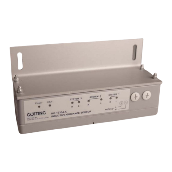
Device Description HG G-19334-A 2.3 LEDs on the Front Plate Power SYSTEM 3 SYSTEM 2 SYSTEM 1 HG 19334-A GÖTTING KG INDUCTIVE GUIDANCE SENSOR NODE-ID Celler Str. 5, D-31275 Lehrte LEDs Figure 3 On the front plate you can find two LEDs per antenna system (red + green) that indi- cate the zero crossing point of the difference signal (both LEDs are lit at once). -
Page 8: Canopen® Interface
Device Description HG G-19334-A Connector Function ST1 (plug) — A-coded ST2 (socket) Shielding A-coded CAN_GND / GND ST3 (plug) CAN_H CAN_L Pin allocations ST1, ST2 and ST3 Table 3 2.5 CANopen® Interface The transfer rate has to be selected by using the serial monitor (see 3 on page 23) or the corresponding SDOs. -
Page 9: Synchronous Identifier
Device Description HG G-19334-A Value Type Value range Function signed 8 -128 ... +127 Lateral deviation left system [mm] signed 8 -128 ... +127 Lateral deviation center system [mm] signed 8 -128 ... +127 Lateral deviation right system [mm] Status unsigned 8 0 ... -
Page 10: Description Of Service Data Objects (Sdos)
Device Description HG G-19334-A Device state Code stopped 0x04 pre-operational 0x7f operational 0x05 CAN: Heartbeat device states Table 7 2.5.4 Description of Service Data Objects (SDOs) To access the object directory the service data object (SDO) is used. An SDO is trans- ferred with an acknowledgement, i.e. -
Page 11: Communication Specific Entries
Device Description HG G-19334-A 2.5.5.1 Communication Specific Entries Communication Specific Entries located from 0x1000 to 0x1FFF Index Subindex Access Content EEProm 0x1000 Device Type 0x1001 Error Register 0x1005 COB ID Sync Message 0x1008 Number of Entries of Device Name Device Name 1... - Page 12 Device Description HG G-19334-A Communication Specific Entries located from 0x1000 to 0x1FFF Index Subindex Access Content EEProm 0x1801 Number of entries of Transmit PDO_2 COB-ID Transmission Type Inhibit Time Event Time 0x1A00 Number of Objects mapped to Transmit PDO_1 Specification of Appl.
-
Page 13: Manufacturer Specific Entries
Device Description HG G-19334-A 2.5.5.2 Manufacturer Specific Entries Manufacturer specific entries from 0x2000 Index Subindex Access Content EEProm 0x2000 Number of Parameter Detect Level Offset Left Offset Center Offset Right 0x2001 Number of Parameter Node Baud rate ... -
Page 14: Canopen Object Dictionary
Device Description HG G-19334-A 2.5.5.4 CANopen Object Dictionary 2.5.5.4.1 Device Type Index Subindex Name Type Attr. Default Meaning 0x1000 Device Type unsigned 32 0x00050191 Digital/analog inputs - DS 401 CAN: Device Type Table 12 2.5.5.4.2 Error Register Index Subindex Name Type Attr. -
Page 15: Software Version
Device Description HG G-19334-A 2.5.5.4.6 Software Version Index Subindex Name Type Attr. Default Meaning 0x100A Software Vis.-String „1.00“ „Version of the Version controller firm- ware“ CAN: Software Version Table 17 2.5.5.4.7 Save Parameter Index Sub Index Name Type Attr. Default... -
Page 16: Identity Object
Device Description HG G-19334-A 2.5.5.4.10 Identity Object Index Sub Index Name Type Attr. Default Meaning 0x1018 Identity unsigned 8 0x03 Number of sub Object indexes Vendor ID unsigned 32 0x00000202 Manufacturer number assigned by CiA Product unsigned 32 0x00019334 Name of the... -
Page 17: Transmit Pdo_2 Parameter
Device Description HG G-19334-A 2.5.5.4.12 Transmit PDO_2 Parameter Index Sub Index Name Type Attr. Default Meaning 0x1801 TxPDO_2 unsigned 8 0x04 Number of sub Parameter indexes COB ID unsigned 32 0x40000280 PDO_2 valid, + Node-ID ID = 0x280 + Node-ID... -
Page 18: Mapping Txpdo_2
Device Description HG G-19334-A 2.5.5.4.14 Mapping TxPDO_2 Index Sub Index Name Type Attr. Default Meaning 0x1A01 number of unsigned 8 0x07 Number of sub mapped indexes objects 1st mapped unsigned 8 0x64000408 mapped to Index object 0x6400,04 with 8 Bit length (SL) -
Page 19: Manufacture Parameter - Antenna Parameters
Device Description HG G-19334-A 2.5.5.4.15 Manufacture Parameter - Antenna Parameters Index Sub Index Name Type Attr Default Meaning 0x2000 number of unsigned 8 0x04 Number of sub parameter indexes Detect level unsigned 8 Detection thresh- Offset left signed 8 Offset left sys-... -
Page 20: Manufacture Parameter - Node Parameters
Device Description HG G-19334-A 2.5.5.4.16 Manufacture Parameter - Node Parameters Index Sub Index Name Type Attr. Default Meaning 0x2001 Number of unsigned 8 0x02 Number of sub Parameter indexes Node Baud- unsigned 8 0x04 125 Kbaud *) rate Node Config... -
Page 21: Bit Analog Inputs (Transmitted In Txpdo 1 And Txpdo 2)
Device Description HG G-19334-A 2.5.5.4.18 8 Bit Analog Inputs (transmitted in TxPDO 1 and TxPDO 2) Index Sub Index Name Type Attr. Default Meaning 0x6400 number of 8 unsigned 8 0x09 Number of 8 bit bit analog analog inputs inputs... -
Page 22: Table 33 Can: Detect Signals And Error Messages
Device Description HG G-19334-A Output byte Data Difference center system (2) high nibble Difference center system (2) low nibble Sum right system (3) high nibble Sum right system (3) low nibble Difference right system (3) high nibble Difference right system (3) low nibble Detect signals and error message high nibble... -
Page 23: Monitor Mode
Monitor Mode HG G-19334-A Monitor Mode The monitor mode is available via the serial interface. The Götting Adapter HG 01933ZA may be used to connect the guidance antenna to a PC. Alternatively you can use a self-made adapter (pin assignment of the serial interface: Table 3 on page 8 / interface parameters: s. -
Page 24: Commands In The Canopen® Menu
Monitor Mode HG G-19334-A 3.2.2 Commands in the CANopen® Menu The CAN menu is structured as follows: Screenshot: CANopen® menu (values exemplary) Figure 7 In the second line the status of the CAN bus is displayed: Bus online changes to Bus offline if e.g. - Page 25 Monitor Mode HG G-19334-A is the cycle time of the TPDO_2 transmission. If both values are 0, TPDO_2 will not be transmitted. changes the so-called Heartbeat time. This is the time interval in which a control message is sent. A value of 0 means that no control message will be sent.
-
Page 26: Technical Data
-20 to +70 Mounting height approx. 35 mm above the energy loop Technical Data Guidance Antenna HG G-19334-A Table 35 4.2 Prerequisites of the Ground Installation The stationary part of the inductive energy transmission has to match the following pre-... -
Page 27: Appendix
Appendix HG G-19334-A Appendix Casing Dimensions of the different Versions including the Mounting Angle HG 19334JA 230 mm ±2 mm 80 mm Power SYSTEM 3 SYSTEM 2 SYSTEM 1 HG 19334-A GÖTTING KG INDUCTIVE GUIDANCE SENSOR NODE-ID Celler Str. 5, D-31275 Lehrte ca. -
Page 28: B Electronic Data Sheet (Eds-File)
Appendix HG G-19334-A HG 19334XA 230 mm ±2 mm 80 mm ca. 35 mm 140 mm Energy Loop Casing dimensions HG 19334XA Figure 10 HG 19334YA 230 mm ±2 mm 80 mm ca. 35 mm 140 mm Energy Loop Casing dimensions HG 19334YA... -
Page 29: List Of Figures
List of Figures HG G-19334-A List of Figures Figure 1 Schematic diagram ................5 Figure 2 Diagram: Voltage curve of the three antenna systems (example) ..5 Figure 3 LEDs ....................7 Figure 4 Placement of the circular connectors..........7 Figure 5 Cycle for starting the monitor mode .......... -
Page 30: List Of Tables
List of Tables HG G-19334-A List of Tables Table 1 Variants overview................. 4 Table 2 Dsiplay options of the CAN LED............7 Table 3 Pin allocations ST1, ST2 and ST3............8 Table 4 CAN: Numerical representation for PDO_1 ......... 9 Table 5 CAN: Meaning of the status bits............ - Page 31 List of Tables HG G-19334-A Table 34 Serial telegram (example) ..............22 HG G-19334-A Table 35 Technical Data Guidance Antenna ..... 26 Table 36 Prerequisites of the Ground Installation ..........26 English, Revision 03, Date: 11.05.2017...
-
Page 32: Handbook Basics
Handbook Basics G-76341-A Handbook Basics In documentations of Götting KG the following symbols and assignments were used at the time of printing this manual: Security advices have the following symbols, depending on the emphasis and the degree of exposure: NOTE! ATTENTION! CAUTION! -
Page 33: Copyright And Terms Of Liability
Copyright and Terms of Liability HG G-19334-A Copyright and Terms of Liability 9.1 Copyright This manual is protected by copyright. All rights reserved. Violations are subject to pe- nal legislation of the Copyright. 9.2 Exclusion of Liability Any information given is to be understood as system description only, but is not to be taken as guaranteed features.
Need help?
Do you have a question about the HG G-19334-A and is the answer not in the manual?
Questions and answers