Table of Contents
Advertisement
Quick Links
Device Description
Positioning and Identification
English, Revision 02
Date: 20.01.2015
Götting KG, Celler Str. 5, D-31275 Lehrte - Röddensen (Germany), Tel.: +49 (0) 51 36 / 80 96 -0,
Fax: +49 (0) 51 36 / 80 96 -80, eMail: techdoc@goetting.de, Internet: www.goetting.de
Antenna
— RS232 —
HG 71450-A
Dev. by:
Author(s):
D.F. / T.N. / W.M.
RAD / A.F. / L.S.
HG 71450-A
Advertisement
Chapters
Table of Contents

Related Manuals for Gotting HG 71450-A


Summary of Contents for Gotting HG 71450-A
- Page 1 Device Description HG 71450-A Positioning and Identification Antenna — RS232 — HG 71450-A English, Revision 02 Dev. by: D.F. / T.N. / W.M. Date: 20.01.2015 Author(s): RAD / A.F. / L.S. Götting KG, Celler Str. 5, D-31275 Lehrte - Röddensen (Germany), Tel.: +49 (0) 51 36 / 80 96 -0,...
-
Page 2: Table Of Contents
Contents HG 71450-A Contents Identification Systems ............4 Application Examples for the Automation......... 4 ISystem Configuration............. 5 Functional Description ............5 1.3.1 General Functional Description ............5 1.3.2 Reception Ranges and Function ............ 6 1.3.3 Signals and Timing ................ 8 Components and Operation .......... - Page 3 Contents HG 71450-A Monitor Programme .............. 25 4.2.1 Programming of a Transponder Type HG 71325 ......26 4.2.2 Update of the Internal Software (Firmware) ........27 Technical Data ..............29 Identifying Antenna G 71450-A..........29 Parallel Converter ..............30 List of Pictures ..............31 List of Tables ..............
-
Page 4: Identification Systems
Identification Systems HG 71450-A Identification Systems To ensure that the operating procedure is working properly, the data transmission be- tween different objects (die carrier, tools, vehicles etc.) and the control system is de- cisive. Mobile objects have to be identified and positioned fast and safely. -
Page 5: Isystem Configuration
Identification Systems HG 71450-A System Configuration Reading Station Interpreter Serial output of the read out transponder code and the positioning impulse Reading antenna Data carrier System configuration Figure 1 1.3 Functional Description 1.3.1 General Functional Description When the antenna crosses a transponder it supplies it with energy by an alternating electromagnetic field. -
Page 6: Reception Ranges And Function
Identification Systems HG 71450-A 1.3.2 Reception Ranges and Function Positioning is carried out according to the field compensation method. In the center of the reading antenna the resulting field for the transponder is erased. This data-free range D, in which no telegrams are output, has a width of 25 to 30 mm at nominal read- ing height S, see Figure 2. - Page 7 Identification Systems HG 71450-A Direction of travel F Reading antenna Line C Offset (Z) Line A Transponder Area II Area I Activation of the positioning pulse (dependent on the direction of travel F and the offset from line A) Core area of the reading antenna with explanation of the positioning pulse...
-
Page 8: Signals And Timing
Identification Systems HG 71450-A 1.3.3 Signals and Timing Direction of travel Reading antenna underneath the vehicle Area I Area II Transponder Reception ranges Antenna length Signals and Timing Data-free range (reception gap) Serial Data Data Security Midpoint Crossover = Positioning pulse time (Duration of the midpoint crossover pulse) = 100 ms... -
Page 9: Components And Operation
Components and Operation HG 71450-A Components and Operation 2.1 Components in the Ground (Transponders) Götting transponders are applied as reference markers within the ground. The system is compatible to all transponders of type G 713XX used so far (depending on the in- stalled version of the reading antenna). -
Page 10: Leds
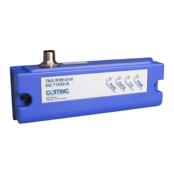
Components and Operation HG 71450-A 2.2.2 LEDs 4 LEDs are provided for function control: Signification Indicates operating voltage applied flashes, if a transponder approaches (area I in Figure 3 on page 6) is lit constantly, if the transponder is read reliably... -
Page 11: Table 3 Options For Adjustments By The Dip- Switches Of The Antenna Board
Components and Operation HG 71450-A From the following table you can see which kind of adjustments of the RS 232 interface can be set via the DIP-switches SW1 to SW8. SW1: Parity EVEN *) SW2: Baud rate See Table 3 on page 11... -
Page 12: Telegram Setup Ascii Coding (Sw5 = On)
Components and Operation HG 71450-A 2.2.5.2 Telegram Setup ASCII Coding (SW5 = ON) Example: Check sum (4 Bit hex-coded) Code D3...D0 Code D7...D4 (ASCII hex-coded) Code D11...D8 Code D15...D12 STX Start character (STX = 02 Hex) Example for a ASCII telegram setup... -
Page 13: Positioning Pulse
Components and Operation HG 71450-A Sum of A , and P results in 0 (Mod256). Example: Bit sequence: 0000 0111 0000 1011 Transponder code 16 bit) 070 in the tran- sponder The following bytes will be output: Character Hex-Value Example telegram binary coded... -
Page 14: Transponder Programming
Components and Operation HG 71450-A 2.2.8 Transponder Programming You can program Transponders that are placed either in area I or area II but not in the data-free range (see Figure 2 on page 6) using serial commands structured as shown in Table 7 on page 14 and Table 8 on page 15. -
Page 15: Telegram Structure (Antenna -> Host) In Case The Transponder Wasn't Programmed
Components and Operation HG 71450-A Binary telegram with fixed start character, 2 data bytes and a check sum. Character Meaning Type Value range Start character Unsigned char 0x11 Code (Hi) Unsigned char Transponder code to be programmed Code (Lo Unsigned char 0x00 …... -
Page 16: Serial/Parallel Interface Hg 06150Y (Optional)
Components and Operation HG 71450-A Binary -Telegram with fixed start character, 2 data bytes and a check sum. Character Meaning Type Value range Start character Unsigned char 0x01 Code (Hi) Unsigned char Last read transponder code Code (Lo Unsigned char 0x00 …... - Page 17 Components and Operation HG 71450-A From the data stream the code will be converted into a 16 bit parallel output. The code is located at the outputs until a new code is received. Furthermore, 50ms after the ar- riving of the codebits a Data_Ready_Impuls (duration: 100ms) is created. A new Data_Ready_Impuls will only be created at a code change.
-
Page 18: Mounting And Setup
Mounting and Setup HG 71450-A Mounting and Setup 3.1 Testing a Transponder It is possible to test the transponders with a reading antenna and a connected PC (see section 4.2 on page 25). 3.2 Mounting Transponder Range and positioning accuracy will be influenced by... -
Page 19: Reading Antenna
Mounting and Setup HG 71450-A 3.3 Reading Antenna 3.3.1 Mounting Drills G 71450-A Mounting of the identifying antenna: Position and size of the drilling Figure 11 All indications refer to the position of the ferrite rod in the antenna: Direction of Travel... -
Page 20: Connection
Mounting and Setup HG 71450-A NOTE! If several antennas are applied within one installation they have to be mounted in a minimum distance of 1500 mm to one another to guarantee a smooth production flow 3.3.2 Connection Connection wires are not part of the scope of supply. Figure 6 on page 9 indicates which kind of cable construction can be applied. -
Page 21: Maintenance
Mounting and Setup HG 71450-A Connectors of the Mounting Bar Casing Code Bit 6 Code Bit 7 Code Bit 8 Code Bit 9 Code Bit 10 Code Bit 11 Rx+ (RS 232 Input) Code Bit 12 n. c. Code Bit 13... - Page 22 Mounting and Setup HG 71450-A English, Revision 02, Date: 20.01.2015...
-
Page 23: Software
Software HG 71450-A Software Transponder Programming and Update of the Internal Software For the realization of these requirements the reader G 71450-A has to be set to the monitor mode, i. e. connect the serial interface of a PC / laptop with the appropriate pins (Rx and Tx, see table Table 1 auf Seite 9) of the reading device. -
Page 24: Parameter Settings
Software HG 71450-A Now check in the window connections if there is a marker before HyperTer- minal (yes = ; no = ). If yes, the program is installed on your system. Then click on (twice) and switch to the next section. If not, set the marker with... -
Page 25: Monitor Programme
Software HG 71450-A Select Properties from the menu File (or click the icon ). The following window will open: Choose the respective port via the direct connection in Connect using in the submenu. Confirm with . Save the altered values if you are asked for it when terminating HyperTerminal. -
Page 26: Programming Of A Transponder Type Hg 71325
Software HG 71450-A 4.2.1 Programming of a Transponder Type HG 71325 By using enter the desired transponder code hexadecimal or by using decimal. Hold the transponder to the reading device, according to the sketch in Figure 16. ... -
Page 27: Update Of The Internal Software (Firmware)
Software HG 71450-A 4.2.2 Update of the Internal Software (Firmware) First of all check the current firmware version by input of ---------------- Transponder- Reader HG71450 Version 1.10 (c) Goetting KG ---------------- 71450A11.10B 30.01.03 ---------------- Modul Date X39300W5 300103 I39300W5... - Page 28 Software HG 71450-A Afterwards it is possible to load the new firmware by ASCII upload. Using HyperTerminal you transmit the file in the following way: In the menu transmission choose the subitem Send Textfile. The follow- ing window will open: Switch to the directory or to the data carrier in which the downloaded files are stored and choose the corresponding firmware file (e.g.
-
Page 29: Technical Data
Technical Data HG 71450-A Technical Data 5.1 Identifying Antenna G 71450-A Identifying Antenna Dimensions See Figure 6 on page 9 Casing Polycarbonat (PC) Current consumption 100 mA Operating Voltage Range 22 to 28 V (max. ripple 10 %) Relative humidity at 25... -
Page 30: Parallel Converter
Technical Data HG 71450-A Identifying Antenna Minimum distance between two 1500 mm reading stations Environmental temperature 0 to +50 Storage temperature -20 to +70 5.2 Parallel Converter Parallel Converter G 06150Y (optional) Casing Mounting rail casing 28-pin 75 x 75 x 47,5 mm L x W x H Supply 24 V ±10 %, approx. -
Page 31: List Of Pictures
List of Pictures HG 71450-A List of Pictures Figure 1 System configuration ................5 Figure 2 Detection Ranges I and II, data-free range and nominal reading distance S, side view ................6 Figure 3 Detection ranges, top view..............6 Figure 4 Core area of the reading antenna with explanation of the positioning pulse (viewed from the top) .............. -
Page 32: List Of Tables
List of Tables HG 71450-A List of Tables Table 1 Pin allocation of the 5-pole circular connector ........9 Table 2 Signification of the 4 LEDs..............10 Table 3 Options for adjustments by the DIP- switches of the antenna board 11 Table 4 Baud rate adjustment via SW2 and SW3........... -
Page 33: Index
Index HG 71450-A Index application examples 4 maintenance 21 monitor program terminal settings 24 mounting drill holes 19 Company names 35 Copyright 35 range 18 reading antenna 19 DIP-Switches 10 reception ranges 6 environmental influences 18 serial/parallel interface Exclusion of Liability 35... -
Page 34: Handbook Conventions
Handbook Conventions HG 71450-A Handbook Conventions In documentations of Götting KG the following symbols and assignments are being used at the time of printing this manual: Security advices have the following symbols, depending on the emphasis and the degree of exposure:... -
Page 35: Copyright And Terms Of Liability
Copyright and Terms of Liability HG 71450-A 10 Copyright and Terms of Liability 10.1 Copyright This manual is protected by copyright. All rights reserved. Violations are subject to pe- nal legislation of the Copyright. 10.2 Exclusion of Liability Any information given is to be understood as system description only, but is not to be taken as guaranteed features.
Need help?
Do you have a question about the HG 71450-A and is the answer not in the manual?
Questions and answers