Table of Contents
Advertisement
Quick Links
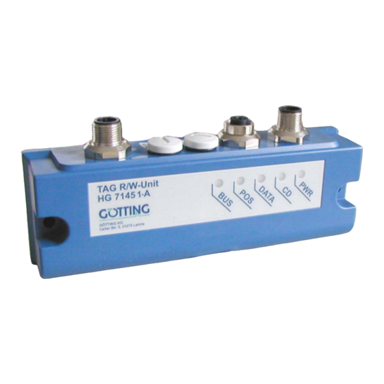
Device Description
Positioning and Identification
English, Revision 03
Date: 07.02.2012
Götting KG, Celler Str. 5, D-31275 Lehrte - Röddensen (Germany), Tel.: +49 (0) 51 36 / 80 96 -0,
Fax: +49 (0) 51 36 / 80 96 -80, eMail: techdoc@goetting.de, Internet: www.goetting.de
Antenna
— Profibus —
HG 71451-A
Dev. by:
Author(s):
D.F. / T.N. / W.M.
RAD / A.F. / L.S.
HG 71451-A
Advertisement
Chapters
Table of Contents

Related Manuals for Gotting HG 71451-A


Summary of Contents for Gotting HG 71451-A
- Page 1 Device Description HG 71451-A Positioning and Identification Antenna — Profibus — HG 71451-A English, Revision 03 Dev. by: D.F. / T.N. / W.M. Date: 07.02.2012 Author(s): RAD / A.F. / L.S. Götting KG, Celler Str. 5, D-31275 Lehrte - Röddensen (Germany), Tel.: +49 (0) 51 36 / 80 96 -0,...
-
Page 2: Table Of Contents
Transmission Range and Function ..........6 1.4.3 Signals and Timing ................ 7 Components and Operation ..........8 Components in the Ground (Transponders) ......8 Identifying Antenna HG 71451-A (Profibus) ......8 2.2.1 Pin Allocations................9 2.2.2 LEDs ................... 10 2.2.3 Turn-on Characteristics ............... - Page 3 Contents HG 71451-A Identification Antenna HG 71451-A ........24 GSD File (Antenna HG 71451-A with Profibus)....25 List of Pictures ..............26 List of Tables ..............27 Index ................28 Handbook Conventions............ 29 Copyright and Terms of Liability ........30 11.1 Copyright................
-
Page 4: Identification Systems
1.2 System Components In order to create a whole positioning und identification system, transonders are need- ed. The antenna HG 71451-A fits the following types: Transponder HG 71325 (free codable) / HG 71370 (switch transponder) Frequency... -
Page 5: System Configuration
Identification Systems HG 71451-A 1.3 System Configuration Reading Station Interpreter Serial output of the read out transponder code and the positioning impulse Reading antenna Data carrier System configuration Figure 1 1.4 Functional Description 1.4.1 General Functional Description When the antenna crosses a transponder it supplies it with energy by an alternating electromagnetic field. -
Page 6: Transmission Range And Function
Identification Systems HG 71451-A 1.4.2 Transmission Range and Function The field intensity of the magnetic alternating field decreases with an increasing dis- tance between transponders and reading antenna. Thus the information exchange is only feasible within a certain area. The field length L and the field width B of the transmission range (see Figure 2 auf Seite 6) will be defined via the parallel centre line through the reading antenna (road). -
Page 7: Signals And Timing
Identification Systems HG 71451-A 1.4.3 Signals and Timing With the transponders G 71310, G 71320 and G 71325. Signals and Timing Figure 3 Initially the data are insecure and the signal strength is still small (range II). Approach- ing further the signals of the data become stronger and can be read completely. The loss of the interception area is detected via the controller in that the thresholds are reached (3 and 4). -
Page 8: Components And Operation
HG 71370-W is able to change the positioning mode. The transponder code provides 16 Bit serially or parallel. 2.2 Identifying Antenna HG 71451-A (Profibus) The antenna system is in a 53 x 31 x 156.5 mm casing (polycarbonate). The antenna is connected by 5-pole cables. -
Page 9: Pin Allocations
Pin Allocations Allocation POSI out (20 mA) TxD (RS 232) RxD (RS 232) GND (Data and Supply) Pin alloc. of the 5-pin circular connector ST1 (pin, HG 71451-A) Table 2 Allocation Bus +5 V Bus A Bus B Bus GND Pin alloc. -
Page 10: Leds
Blinks once if an address >126 was adjusted Blinks twice or three times, if internal profibus errors occur Shines on data exchange with profibus- master Significance of the 5 LEDs HG 71451-A Table 5 2.2.3 Turn-on Characteristics On activation of power supply for the duration of the reset the positioning output is ac- tive (approximately 500 ms) for the duration of the reset. -
Page 11: Table 6 Structure Of The 3 Profibus Input Bytes
Components and Operation HG 71451-A Simple reading of the antenna with 3 input bytes according to the following table Byte # Length Type Sequence Signification 2 Byte unsigned int Lo Byte read transponder code Hi Byte 1 Byte unsigned char... -
Page 12: Table 9 Structure Of The 3 Profibus Input Bytes
Components and Operation HG 71451-A Read antenna with 3 input bytes (Table 9) and transponder programming with 3 output bytes (table 17) Byte # Length Type Sequence Significance 2 Byte unsigned int Lo Byte read Transponder code Hi Byte 1 Byte... -
Page 13: Profibus Address
Components and Operation HG 71451-A Priority Name Significance 0x01 PROG Transponder programming 0x02 Internal deletion of the last transponder code 0x04 Currently not allocated 0x08 0x10 0x20 0x40 0x80 Significance of the instruction bit Table 12 Programming A Transponder Using The Profibus Internface For the positioning of the transponder to the reading antenna q. -
Page 14: Posipuls
Components and Operation HG 71451-A The data is put out ASCII coded , the single sets are seperated by a comma. Data lines are ended by <CR LF> . Data of this format can be recorded with Hyperterm and be saved as a so called CSV file. -
Page 15: Mounting And Setup
Mounting and Setup HG 71451-A Mounting and Setup 3.1 Testing a Transponder It is possible to test the transponders with a reading antenna and a connected PC (q. v. section 4.2 on page 20). 3.2 Mounting Transponder Range and Positioning accuracy will be influenced by... -
Page 16: Mounting In Tough Material (E. G. Tar)
Mounting and Setup HG 71451-A 3.2.2 Mounting in Tough Material (e. g. tar) Protection tube necessary (e. g. of fiber-reinforced plastic material). Choose the diameter of the load accordingly. Arrange the transponders unmounted or vertical in foamed material (otherwise a position error will occur). -
Page 17: Connection
Mounting and Setup HG 71451-A NOTE! If several antennas are applied within one installation they have to be mounted in a minimum distance of 1500 mm to one another to guarantee a smooth production flow. All indications refer to the position of the ferrite rod in the antenna:... -
Page 18: Software
Software HG 71451-A Software Transponder Programming and Update of the Internal Software For the realization of these requirements the antenna has to be set to the monitor mode, i. e. connect the serial interface of a PC / laptop with the appropriate pins (Rx and Tx) of the antenna. -
Page 19: Parameter Settings
Software HG 71451-A Subsequently you will be asked to insert your Setup- CD into your CD- ROM drive. Install the CD and click on icon .Confirm all installation messages. Hyper Terminal will be installed and is then ready for use. -
Page 20: Monitor Program
Software HG 71451-A 4.2 Monitor Program After connection set-up has been effected (see above) enter in the terminal pro- gram. The following display will appear: HG71451 Monitor System 409kHz Profibus address: Current Transponder Code [hex/dez]: 9ABC / 39612 (H)ex Input Transponder Code [0..FFFF]:... -
Page 21: Programming Of A Transponder Type Hg 71325
Software HG 71451-A 4.2.1 Programming of a Transponder Type HG 71325 By using enter the desired transponder code hexadecimal or by using decimal. Hold the transponder to the reading device, according to the sketch in Figure 10. ... -
Page 22: Update Of The Internal Software (Firmware)
Software HG 71451-A 4.2.2 Update of the Internal Software (Firmware) First of all check the current Firmware-version by input of ---------------- Transponder- Reader G71450 Version 1.10 (c) Goetting KG ---------------- 71450A11.10B 30.01.03 ---------------- Modul Date X39300W5 300103 I39300W5 060103... - Page 23 Software HG 71451-A Afterwards it is possible to load the new Firmware by ASCII- Upload. Using HyperTerminal you transmit the file in the following way: In the menu transmission choose the subitem Send Textfile. The follow- ing window will open: Switch to the directory or to the data carrier in which the downloaded files are stored and choose the corresponding firmware- file (e.g.
-
Page 24: Technical Data
PosiPuls 24 V, 20 mA, current limited Minimum distance between two reading 1500 mm stations Environmental temperature 0 to +50 Storage temperature -20 to +70 Technical Data Identification Antenna HG 71451-A Table 14 English, Revision 03, Date: 07.02.2012... -
Page 25: Gsd File (Antenna Hg 71451-A With Profibus)
You can download the latest version of the GSD files from our internet server: http:// www.goetting.de/en/download/. As a search item you have to enter 71451 to down- load only the GSD file for the antenna HG 71451-A. English, Revision 03, Date: 07.02.2012... -
Page 26: List Of Pictures
Length and width of the interception area (view from above)..... 6 Figure 3 Signals and Timing ................7 Figure 4 Antenna dimensions HG 71451-A ............8 Figure 5 Metal-free area around the transponder HG 71325 ......16 Figure 6 Mounting of the identifying antenna: Position and size of the drilling16 Figure 7 Nominal reading distance / position of the antenna ferrite rod .. -
Page 27: List Of Tables
List of Tables Table 1 Available antennas and transponders..........4 Table 2 Pin alloc. of the 5-pin circular connector ST1 (pin, HG 71451-A) ..9 Table 3 Pin alloc. of the 5-pin circular connector ST2 (socket, HG 71451-A1) 9 Table 4 Pin alloc. -
Page 28: Index
Index HG 71451-A Index application examples 4 maintenance 17 monitor program terminal settings 19 mounting drill holes 16 centre deviation 6 Company names 30 Copyright 30 Profibus 8, 25 environmental influences 15 Exclusion of Liability 30 range 15 reading antenna 16... -
Page 29: Handbook Conventions
Handbook Conventions G_71451-A 10 Handbook Conventions In documentations of Götting KG the following symbols and assignments are being used at the time of printing this manual: Security advices have the following symbols, depending on the emphasis and the degree of exposure: NOTE! ATTENTION! CAUTION! -
Page 30: Copyright And Terms Of Liability
Copyright and Terms of Liability HG 71451-A 11 Copyright and Terms of Liability 11.1 Copyright This manual is protected by copyright. All rights reserved. Violations are subject to pe- nal legislation of the Copyright. 11.2 Exclusion of Liability Any information given is to be understood as system description only, but is not to be taken as guaranteed features.
Need help?
Do you have a question about the HG 71451-A and is the answer not in the manual?
Questions and answers