
Related Manuals for KYLAND SICOM3014GV


Summary of Contents for KYLAND SICOM3014GV
- Page 1 SICOM3014GV Industrial Ethernet Switch Hardware Installation Manual Publication Data: Oct. 2018 Version: V1.1...
- Page 2 All rights reserved. No part of this documentation may be excerpted, reproduced, translated, annotated or duplicated, in any form or by any means without the prior written permission of KYLAND Corporation. Copyright © 2018 Kyland Technology Co., Ltd.
- Page 3 Before using the device, read this notice carefully for personal and equipment safety. Please keep the manual for further reference. Kyland is not liable to any personal or equipment damage caused by violation of this notice.
- Page 4 Dispose of the device in accordance with relevant national provisions, preventing environmental pollution. In the following cases, please immediately shut down your power supply and contact your Kyland representative: Water gets into the equipment. Equipment damage or shell damage.
-
Page 5: Table Of Contents
CONTENTS Product Overview ......................1 Structure and Interface ....................2 2.1 Front Panel ........................ 2 2.2 Top Panel ........................3 Mounting ........................4 3.1 Dimension Drawing ....................4 3.2 Mounting Modes and Steps ..................4 3.2.1 Mounting ......................5 3.2.2 Wall Mounting ..................... 5 Connection ........................ -
Page 6: Product Overview
Product Overview Product Overview Managed video surveillance SICOM3014GV Industrial Ethernet Switch applied in the ITS, highway, industrial automation, oil&gas and many other industries. The SICOM3014GV are applicable to harsh and hazardous industrial environments due to its high-performance switching engine, solid closed housing, fanless but heat dissipation-capable single-rib shaped chassis, overcurrent, overvoltage, and EMC protection for power input, and EMC protection of RJ45 ports. -
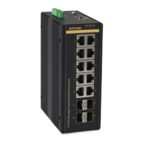
Page 7: Structure And Interface
Structure and Interface Structure and Interface Caution: It is recommended to purchase the port dustproof shield (optional) to keep ports clean and ensure switch performance. 2.1 Front Panel Figure 1 Front Panel Table 2 Description of the Front Panel Identifier Description 11-14 four 100/1000Base-X,10/100/1000Base-T(X) SFP slots... -
Page 8: Top Panel
Structure and Interface 2.2 Top Panel Figure 2 Top Panel Table 3 Description of the Top Panel Identifier Description PWR1 Power terminal block 1 Console Console port Reset Reset button for switch Alarm relay output Grouding screw PWR2 Power terminal block 2... -
Page 9: Mounting
Mounting Mounting 3.1 Dimension Drawing Figure 3 Dimensions (unit: mm) Caution: As part of the heat dissipation system, the switch housing becomes hot during operation. Please use caution when coming in contact and avoid covering the switch housing when the switch is running. -
Page 10: Mounting
Mounting non-condensing) 2) Power requirement: The power input is within the voltage range of the switch. 3) Grounding resistance: <5 4) No direct sunlight, distant from heat source and areas with strong electromagnetic interference. 3.2.1 Mounting DIN-Rail Mounting Step 1: Select the mounting position for the device and guarantee adequate space and heat dissipation . - Page 11 Mounting Figure 5 Wall Mounting...
-
Page 12: Connection
Connection Connection 4.1 10/100/1000Base-T(X) Ethernet Port 10/100/1000Base-T(X) Ethernet port is equipped with RJ45 connector. The port is self-adaptive. It can automatically configure itself to work in 10M, 100M, or 1000M state, full or half duplex mode. The port can also adapt to MDI or MDI-X connection automatically. You can connect the port to a terminal or network device with a straight-through or cross-over cable. -
Page 13: 100/1000Base-X, 10/100/1000Base-T(X) Sfp Slot
Connection Wiring Sequence Figure 7 Connection Using Straight-through/Cross-over Cable Note: The color of the cable for RJ45 connector meets the 568B standard: 1-orange and white, 2-orange, 3-green and white, 4-blue, 5-blue and white, 6-green, 7-brown and white, and 8-brown. 4.2 100/1000Base-X, 10/100/1000Base-T(X) SFP slot 100/1000Base-X, 10/100/1000Base-T(X) SFP slot (gigabit SFP slot) requires an SFP optical/electrical module to enable data transmission. -
Page 14: Gigabit Sfp Optical Module
Connection T-RJ45 T(X) port 4.2.1 Gigabit SFP Optical Module Figure 8 Gigabit SFP Optical Module An SFP optical module is equipped with LC connector, and each port consists of a TX (transmit) port and an RX (receive) port. To enable communication between Device A and Device B, connect the TX port of Device A to the RX port of Device B, and the RX port of Device A to the TX port of Device B, as shown in the following figure. -
Page 15: Gigabit Sfp Electrical Module
Connection 2. View the corresponding connection status LED: If the LED is on, the connection is correct. If the LED is off, the link is not connected. This may be caused by incorrect connection of the TX and RX ports. In this case, swop the two connectors at one end of the fibers. - Page 16 (female) connector cable is required. The RJ45 connector of the cable is connected to the CID port of SICOM3014GV; the DB9 connector of the cable is connected to the PC COM port. The pin assignment of the console cable is shown below:...
-
Page 17: Grounding / Power Terminal Block/ Alarm Terminal Block
Connection RXD (Receive data) RXD (Receive data) TXD (Transmit data) TXD (Transmit data) DGND (Grounding) DGND (Grounding) 4.4 Grounding / Power Terminal Block/ Alarm Terminal Block The alarm relay output contacts are in the middle of the DC terminal block connector as shown in the figure below. -
Page 18: System Reset
Connection Note: Cross-sectional area of the chassis grounding cable>2.5mm ; grounding resistance<5. Caution: The switch supports power input (as listed in Table 1). Before connecting the device to power supply, make sure that the power input meets the power requirement. If connected to an incorrect power input, the device may be damaged. -
Page 19: Leds
LEDs LEDs Table 7 Front Panel LEDs LED Name Indicator /color Condition On Green PWR1/ PWR2 power line has power PWR1/ PWR2 PWR1/ PWR2 power line disconnect or does not have On Red Ethernet link fails, alarm or power failure alarm occurs Alarm No Ethernet link fails and no power failure alarm 10/100/1000Base-T(X) -
Page 20: Switch Access
Switch Access Switch Access You can access the switch in any of the following ways: 6.1 Access through Console Port Step 1: Connect the console port of the switch to the 9-pin serial port of a PC with the RJ45-DB9 console cable. Step 2: Open Hyper Terminal in Windows OS. - Page 21 Switch Access Figure 18 Selecting a Serial Port Note: To confirm the communication port in use, right-click [My Computer] and select [Property]. Click [Hardware] → [Device Manager] → [Port] to view the communication port. Step 5: Set port parameters (Bits per second: 115200, Data bits: 8, Parity: None, Stop bits: 1 and Flow control: None), as shown in the following figure.
-
Page 22: Access Through Telnet
Step 2: On the Windows desktop, click Start and Run. The Run dialog box is displayed. Enter "telnet IP address". For example, if the IP address of the device is 192.168.0.2 (default IP address of a Kyland switch), enter "telnet 192.168.0.2" in the dialog box. Figure 20 Access through Telnet Step 3: Click OK. -
Page 23: Access Through Web
Switch Access 6.3 Access through Web Step 1: Connect the network port of the PC to the RJ45 port of the switch with an RJ45-RJ45 cable. Step 2: Enter the IP address of the switch in the address box of the browser. The user login interface is displayed. -
Page 24: Basic Features And Specifications
Basic Features and Specifications Basic Features and Specifications Power Requirements Power Identifier Rated Voltage Range Maximum Voltage Range 24VDC 12 -58 VDC Terminal block 6-pin 3.81mm-spacing plug-in terminal block Rated Power Consumption Rated power consumption 17Watts Physical Characteristics Housing Aluminum Installation DIN-rail and Wall mounting Dimensions (W×H×D) - Page 25 FAX: +86-10-88796678 Website: http://www.kyland.com Email: support@kyland.com For more information about KYLAND products, please visit our website: http://www.kyland.com...
Need help?
Do you have a question about the SICOM3014GV and is the answer not in the manual?
Questions and answers