
Related Manuals for KYLAND SICOM6448G Series


Summary of Contents for KYLAND SICOM6448G Series
- Page 1 SICOM6448G Series Industrial Ethernet Switches Hardware Installation Manual Publication Data: Nov. 2016 Version: V1.0...
- Page 2 All rights reserved. No part of this documentation may be excerpted, reproduced, translated, annotated or duplicated, in any form or by any means without the prior written permission of KYLAND Corporation. Copyright © 2016 Kyland Technology Co., Ltd.
- Page 3 Before using the device, read this manual carefully for personal and equipment safety. Please keep the manual for further reference. Kyland is not liable to any personal or equipment damage caused by violation of this notice.
- Page 4 Specification of the internal fuses in this equipment: 3.15A/300V. In the following cases, please immediately shut down your power supply and contact your Kyland representative: Water gets into the equipment. Equipment damage or shell damage.
-
Page 5: Table Of Contents
Contents 1 Product Overview .......................2 2 Structure and Interface .......................3 2.1 Front Panel ........................3 2.2 Rear Panel ........................4 3 Switch Installation .......................5 3.1 Dimension Drawing ......................5 3.2 Mounting Modes and Steps ..................6 4 Connection .........................9 4.1 10/100/1000Base-T(X) Ethernet Port ................9 4.2 1000Base-X, 10/100/1000Base-T(X) SFP slot ............ -
Page 6: Product Overview
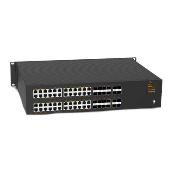
1 Product Overview SICOM6448G includes a series of high-performance gigabit industrial Ethernet switches developed by Kyland. The series devices are applicable to rail transit(ground system), Petrochemical core switching system. The series switches support high density gigabit ports and flexible configuration of gigabit optical ports and gigabit electrical ports. All the devices meet the requirements stipulated in the EN50121-4 and other industrial standards. -
Page 7: Structure And Interface
Structure and Interface 2 Structure and Interface Caution: It is recommended to purchase the port dustproof shield (optional) to keep ports clean and ensure device performance. 2.1 Front Panel Figure 1 Front Panel Table 2 Description of the Front Panel Identifier Description Alarm... -
Page 8: Rear Panel
Structure and Interface 2.2 Rear Panel Figure 2 Rear Panel Table 3 Description of the Rear Panel Identifier Description GE(1-16) Sixteen 10/100/1000Base-T(X) Ethernet interface; GX/GE(17-24) Eight 1000Base-X, 10/100/1000Base-T(X)Combo interface; XG(1-4) Four 10GBase-X SFP+ interface; FAULT Alarm terminal block; Twenty-four 1000Base-X, 10/100/1000Base-T(X)SFP GX(25-48) interface;... -
Page 9: Switch Installation
Switch Installation 3 Switch Installation 3.1 Dimension Drawing Figure 3 Dimensions (unit: mm) Caution: As part of the heat dissipation system, the switch housing becomes hot during operation. Please use caution when coming in contact and avoid covering the switch housing when the switch is running. -
Page 10: Mounting Modes And Steps
Switch Installation 3.2 Mounting Modes and Steps The series switches support rack mounting by front/rear panel. The following uses mounting by front panel as an example to describe mounting steps. The steps for mounting by rear panel are similar to those for mounting by front panel. Before installation, make sure that the following requirements are met. - Page 11 Switch Installation brackets. If there are screws inserted in the screw holes, remove the screws and keep them for future use. As shown in the following figure, use four screws to secure two mounting brackets to the switch respectively. Screw holes for rear panel mounting Screw holes for rear panel mounting...
- Page 12 Switch Installation The mounting brackets can only fix the switch and can not bear the load. Please select a rack with a tray or rail for installation. In a high vibration environment, the front and rear panels of the device are secured to the rack at the same time to ensure safe use.
-
Page 13: Connection
Connection 4 Connection 4.1 10/100/1000Base-T(X) Ethernet Port 10/100/1000Base-T(X) Ethernet port is equipped with RJ45 connector. The port is self-adaptive. It can automatically configure itself to work in 10M, 100M, or 1000M state, full or half duplex mode. The port can also adapt to MDI or MDI-X connection automatically. You can connect the port to a terminal or network device with a straight-through or cross-over cable. -
Page 14: 1000Base-X, 10/100/1000Base-T(X) Sfp Slot
Connection Wiring Sequence Figure 7 Connection Using Straight-through/Cross-over Cable Note: The color of the cable for RJ45 connector meets the 568B standard: 1-orange and white, 2-orange, 3-green and white, 4-blue, 5-blue and white, 6-green, 7-brown and white, and 8-brown. 4.2 1000Base-X, 10/100/1000Base-T(X) SFP slot 1000Base-X, 10/100/1000Base-T(X) SFP slot (gigabit SFP slot) requires an SFP optical/electrical module to enable data transmission. - Page 15 Connection IG-FSFP-S-LX-LC-1310-10 100Base-FX port SM 1310nm 10km IGSFP-SD-S-LC-1310T/155 T1310nm 1000Base-X port 20km 0R-20 R1550nm IGSFP-SD-S-LC-1550T/131 T1550nm 1000Base-X port 20km 0R-20 R1310nm IGSFP-SD-S-LC-1310T/155 T1310nm 1000Base-X port 40km 0R-40 R1550nm IGSFP-SD-S-LC-1550T/131 T1550nm 1000Base-X port 40km 0R-40 R1310nm IGSFP-SD-S-LC-1490T/155 T1490nm 1000Base-X port 80km 0R-80 R1550nm IGSFP-SD-S-LC-1550T/149...
- Page 16 Connection used in pairs. For example, modules 7 and 8 are single-mode and LC-interface modules with a transmission distance of 20 km. For the central wavelength of module 7, the transmitting end is 1310 nm and the receiving end is 1550 nm. For the central wavelength of module 8, the transmitting end is 1550 nm and the receiving end is 1310 nm.
-
Page 17: 1000Base-X, 10/100/1000Base-T(X) Combo Port
Connection Identify the RX port and TX port of an SFP optical module: 1. Insert the two connectors in one end of two fibers into the SFP module, and those in the other end into the peer module. 2. View the corresponding connection status LED: If the LED is on, the connection is correct. -
Page 18: 10Gbase-X Sfp+ Port
Connection …… …… …… 4.4 10GBase-X SFP+ port 10GBase-X SFP+ slot (10GBase-X SFP+ slot) requires an SFP+ optical module to enable data transmission. The following table lists the 10GBase-X SFP+ optical modules (optional) supported by the series switches. Table 7 SFP+ optical module Central Transmission Model... -
Page 19: Grounding
Connection serial port of a PC, and the other end is crimped RJ45 connector to be inserted into the console port of the switch. Figure 12 Wiring Sequence of DB9-RJ45 Console Cable Table 8 Pin Definitions of DB9 Port (9-Pin Serial Port) and RJ45 Port (Console Port) DB9 Port (9-Pin Serial Port) RJ45 Port (Console Port) Signal... -
Page 20: Power Terminal Block
Connection 4.7 Power Terminal Block There is a power terminal block on the rear panel of the device. You need to connect the power wires to the terminal block to provide power to the device. The device supports single (PWR1) and redundant (PWR1 and PWR2) power supply with a 5-pin 5.08mm-spacing plug-in terminal block. -
Page 21: Alarm Terminal Block
Connection the wires. Step 4: Insert the terminal block with the connected wires into the terminal block socket on the device. Step 5: Connect the other end of the power wires to the external power supply system according to the power supply requirements of the device. View the status of the power LEDs on the front panel. - Page 22 Connection Figure 14 Alarm Terminal Block (socket) Electrical parameters of the relay: Max Switch Voltage: 250VAC/220VDC; Max Switch Current: 2A Max Switching Power: 60W Dielectric Strength: 2KV Note: Pin 1 and pin 2 are normally-open contacts; pin 2 and pin 3 are normally-closed contacts. When the switch works properly, pin 1 and pin 2 are closed, pin 2 and pin 3 are open;...
-
Page 23: Leds
LEDs 5 LEDs Table 12 Front Panel LEDs State Description Power 1 is connected and operates properly. Power 1 LED-PWR1 Power 1 is not connected or operates abnormally. Power 2 is connected and operates properly. Power 2 LED-PWR2 Power 2 is not connected or operates abnormally. Blinking The CPU operates properly. - Page 24 LEDs Table 13 Rear Panel LEDs State Description LED 1 indicate the status of the lower slot, while LED 2 indicate the status of the upper slot. Effective port connection and 1000M working Yellow on state (1000Base-TX) Effective port connection and 10/100M working Green on state (10/100Base-T(X)) 10/100/1000Base-T(X) Ethernet port...
- Page 25 LEDs Effective port connection 1000Base-X, 10/100/1000Base-T(X) SFP Blinking Ongoing network activities slot connection status LED No effective port connection 10G working state (10GBase-X) 10GBase-X SFP+ slot speed LED 1000M working state (1000Base-TX) or no connection Effective port connection 10GBase-X SFP+ slot connection status Blinking Ongoing network activities No effective port connection...
-
Page 26: Switch Access
Switch Access 6 Switch Access You can access the switch in any of the following ways: 6.1 Access through Console Port Step 1: Connect the console port of the switch to the 9-pin serial port of a PC with the delivered DB9-RJ45 console cable. - Page 27 Switch Access Figure 16 Selecting a Serial Port Note: To confirm the communication port in use, right-click [My Computer] and select [Property]. Click [Hardware] → [Device Manager] → [Port] to view the communication port. Step 5: Set port parameters (Bits per second: 115200, Data bits: 8, Parity: None, Stop bits: 1, and Flow control: None), as shown in the following figure.
-
Page 28: Access Through Telnet
Switch Access Figure 17 Setting Port Parameters Step 6: Click OK to enter the switch CLI. Then the following commands can be used to perform operations. Table 14 CLI Commands View Command Description General mode SWITCH>enable Enter the privileged mode. Privileged mode SWITCH#show interface vlan 1 Query the default IP address of the switch. -
Page 29: Access Through Web
Switch Access Step 2: On the Windows desktop, click Start and Run. The Run dialog box is displayed. Enter "telnet IP address". For example, if the IP address of the serial port module is 192.168.0.2 (default IP address of the device), enter "telnet 192.168.0.2" in the dialog box. -
Page 30: Basic Features And Specifications
Basic Features and Specifications 7 Basic Features and Specifications Power Requirements Maximum Voltage Power Identifier Rated Voltage Range Range 100-240VAC, 50/60Hz; HV (220AC/DCW) 85-264VAC/77-300VDC 110-220VDC Terminal block 5-pin 5.08mm-spacing plug-in terminal block Rated Power Consumption Without 10GBase-X SFP+ port : 75W Rated power consumption With 10GBase-X SFP+ port : 85W Physical Characteristics... - Page 31 FAX: +86-10-88796678 Website: http://www.kyland.com Email: support@kyland.com Address: Building No.2, Shixing Avenue 30# shijingshan District, Beijing, China For more information about KYLAND products, please visit our website: http://www.kyland.com...
Need help?
Do you have a question about the SICOM6448G Series and is the answer not in the manual?
Questions and answers