
Related Manuals for KYLAND SICOM3000S


Summary of Contents for KYLAND SICOM3000S
- Page 1 SICOM3000S Industrial Ethernet Switch Hardware Installation Manual Publication Date: May. 2021 Version: V1.1 No.: 112020193...
- Page 2 SICOM3000S Industrial Ethernet Switch Hardware Installation Manual Disclaimer: Kyland Technology Co., Ltd. tries to keep the content of this manual as accurate and as updated as possible. This document is not guaranteed to be error-free, and we reserve the right to amend it without notice to users.
- Page 3 Before using the device, read this notice carefully for personal and equipment safety. Please keep the manual for further reference. Kyland is not liable to any personal or equipment damage caused by violation of this notice.
- Page 4 Dispose of the device in accordance with relevant national provisions, preventing environmental pollution. In the following cases, please immediately shut down the power supply and contact Kyland: Water gets into the device. Device damage or shell damage.
-
Page 5: Table Of Contents
Contents 1 Product Overview ....................... 6 2 Structure and Interface ....................... 7 2.1 Front Panel ......................... 7 2.2 Top Panel ........................8 3 Mounting ..........................9 3.1 Dimension ........................9 3.2 Mounting Modes and Steps ..................9 3.3 DIN Mounting ......................10 4 Connection ........................ - Page 6 8 Basic Features and Specifications ..................29...
-
Page 7: Product Overview
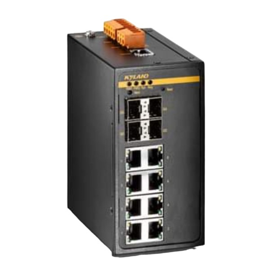
Product Overview 1 Product Overview SICOM3000S series switch is a two-layer network management PoE industrial Ethernet switch developed by Kyland for petroleum and petrochemical, factory automation, intelligent transportation, rail transit and other industries. This series of switches supports DIN rail mounting, provides RJ45 management port, supports Console、Telnet、Web management;... -
Page 8: Structure And Interface
Structure and Interface 2 Structure and Interface Caution: It is recommended to purchase the port dustproof shield (optional) to keep ports clean and ensure switch performance. 2.1 Front Panel Figure 1 Front panel (3) Run LED (1) PWR 1 LED (2) PWR 2 LED (6) Alarm LED (4) Ring status LED (5) Reset button... -
Page 9: Top Panel
Structure and Interface (15) output signal LED (16) input signal LED (17) POE output LED (18) output signal (19) output GND (20) input signal interface interface (21) input GND 2.2 Top Panel Figure 2 Top panel... -
Page 10: Mounting
Mounting 3 Mounting 3.1 Dimension Figure 3 DIN-rail mounting dimension (mm) Caution: As part of the heat dissipation system, the switch housing becomes hot during operation. Please do not cover the switch housing when the switch is running. The figures in this manual are only for reference. -
Page 11: Din Mounting
Mounting interference. 5) The installation environment should meet the requirements of the authority, do not touch the equipment directly by hand, avoid causing personal injury. 6) Only professionals or trained and qualified personnel can perform installation, replacement and maintenance operations for this switch. 3.3 DIN Mounting ... - Page 12 Mounting Figure 5 DIN-rail dismounting...
-
Page 13: Connection
Connection 4 Connection 4.1 10/100/1000Base-T(X) ethernet port 10/100/1000Base-T(X) Ethernet port uses standard RJ45 connector. The port supports self-adaptive and it can be automatically configured to 10M/100M/1000M, full or half duplex mode. The port can also support auto MDI/MDI-X, that is connect the port to a terminal or network device with a straight-through or cross-over cable. -
Page 14: Poe Function
Connection Wiring Sequence Figure 7 10/100Base-T(X) RJ45 Connection Using Straight-through/Cross-over Cable Note: The color of the cable for RJ45 connector follow standard 568B (1-orange and white,2-orange, 3-green and white, 4-blue, 5-blue and white, 6-green, 7-brown and white, and 8-brown.) 4.2 POE Function This device power the external PD (Power Device) through 10/100 Base-T (X) or 10/100/1000 Base-T(X) ethernet interface as PSE (Power Sourcing Equipment). -
Page 15: 1000Base-X, 10/100/1000Base-T(X)Sfp Interface
Connection RJ45 interface Transmit/Receive Data Transmit/Receive Data (TRD1+) (TRD0+) Transmit/Receive Data Transmit/Receive Data (TRD1-) (TRD0-) Transmit/Receive Data Transmit/Receive Data (TRD0+) (TRD1+) Transmit/Receive Data Transmit/Receive Data (TRD3+) (TRD2+) Transmit/Receive Data Transmit/Receive Data (TRD3-) (TRD2-) Transmit/Receive Data Transmit/Receive Data (TRD0-) (TRD1-) Transmit/Receive Data Transmit/Receive Data... -
Page 16: Sfp Optical Module
Connection IGSFP-M-SX-LC-850-0.55 1000Base-X 850nm 0.55km IGSFP-S-LX-LC-1310-10 1000Base-X 1310nm 10km IGSFP-S-LH-LC-1310-40 1000Base-X 1310nm 40km IGSFP-S-ZX-LC-1550-80 1000Base-X 1550nm 80km Note: The switch support optical power detection of SFP port, this function needs SFP module with DDM, if you want to get more detailed information, please contact market or technical engineer. 4.3.1 SFP optical module Figure 8 SFP optical module SFP optical module interface adopts standard LC fiber connector, each interface is... -
Page 17: Console Port
Connection Figure 10 Connecting the SFP Optical Module Confirm the RX port and TX port of an SFP optical module: 1. Insert the two connectors at one end of fibers into the two interfaces of SFP module, and then insert the two connectors at the other end of fibers into the two interfaces at the corresponding end. -
Page 18: Grounding
Connection Figure 11 Console port DB9-RJ45 Console Cable One end of a DB9-RJ45 console cable is crimped RJ45 connector to be inserted into the console port of the switch, and the other end is the DB9 connector to be inserted into the 9- pin serial port of a PC. -
Page 19: Power Terminal Block
Connection The switch provides a grounding screw on the top panel for chassis grounding. After crimping one end of the grounding cable to a cold pressed terminal, fix the grounding screw and connect the other end to the earth firmly. Note: ;... - Page 20 Connection PGND PGND PWR2:- PWR2:N PWR2:+ PWR2:L Wiring and Mounting Step 1: Ground the device properly according to section 4.5. Step 2: Remove the power terminal block from the device. Step 3: Insert the power wires into the power terminal block according to Table 6 and fix the wires.
-
Page 21: Alarm Terminal Block
Connection 4.7 Alarm Terminal Block The alarm terminal block is located on the cover plate of the device for alarm output. When the device works normally, the alarm relay normally-open contact is on, and normally- close contact is off; When an alarm occurs, normally-open contact is off and normally-close contact is on. -
Page 22: Di/Do Interface
Connection Step 3: Insert the alarm terminal block into its socket. Wiring and mounting should meet the following specifications Table 8 Wiring and Mounting Specifications Terminal Block type Torque requirements Cross-sectional area (AWG) Plug-in Terminal Block 4.5-5.0 lb-in 12-24 4.8 DI/DO Interface The input and output terminals are located on the lower right side of the front panel, which provides two low drive input signal acquisition, high drive output ability, the input is optocoupler isolated acquisition, and the output is normally-open and normally-close... -
Page 23: Reset
Reset 5 Reset The reset button is located in the front panel of the device and has the function of restarting and restoring the default configuration. Continue to press the reset button 0.5~3 seconds then release to complete the device restart. Press the reset button continuously for more than 3 seconds then release to restore the default configuration and restart. -
Page 24: Led Status
LED Status 6 LED Status Table 9 LEDs description status Description Power 1 is connected and run normally. Power 1 LED Power 1 is not connected or running abnormally. Power 2 is connected and run normally. Power 2 LED Power 2 is not connected or running abnormally. Blinking The CPU run normally Run LED... - Page 25 LED Status The valid network connection is not established 10/100/1000Base-T(X) Ethernet port 1000M working mode (1000Base-T) speed LED (Yellow) 10/100M working mode or no connection The valid network connection is established 10/100/1000Base-T(X) Ethernet port Blinking Network activity link status LED (Green) The valid network connection is not established POE port supply power normally Ethernet port POE LED-POE...
-
Page 26: Access
Access 7 Access You can access the switch in following three ways: 7.1 Access through Console Port Step 1: Connect the console port of the switch to the 9-pin serial port of a PC with the delivered DB9-RJ45 console cable. Step 2: Open Hyper Terminal in Windows OS. - Page 27 Access Figure 16 Select correct communication port Note: Right-click [My Computer] and select [Property]. Click [Hardware] → [Device Manager] → [Port] to view the communication port. Step 5: Set port parameters (Bits per second: 115200, Data bits:8, Parity: None, Stop bits:1, and Flow control: None), as shown in the below figure.
-
Page 28: Access Through Telnet
Step 2: On the Windows desktop, click Start and Run. Enter "telnet IP address" in the run dialog box. For example, if the IP address of the device is 192.168.0.2 (default IP address of the Kyland switch), enter "telnet 192.168.0.2" in the dialog box. Figure 18 Access through Telnet Step 3: Click OK and you can run the commands in Table 10 to perform operations in the Telnet CLI. - Page 29 Access RJ45 cable. Step 2: Enter the IP address of the switch in the address box of the browser. You can log in to the Web management interface by using default user name "admin" and password "123". Note: IE8.0 or above version is recommended ...
- Page 30 Basic Features and Specifications 8 Basic Features and Specifications Power supply Power identifier Rated Input Voltage Range Maximum Input Voltage Range 48VDC(802.3af) 45-50VDC(802.3af) 53VDC(802.3at) 51-56VDC(802.3at) Terminal Block L16: 5-pin 5.08mm spacing plug-in terminal block Rated Power Consumption Rated power consumption <15W (no PoE) Physical Housing...
Need help?
Do you have a question about the SICOM3000S and is the answer not in the manual?
Questions and answers