Advertisement
Quick Links
DESCRIPTION
Demonstration circuit 2798A is a high voltage, dual-phase
single output boost converter with 10V to 16V input
range. The output voltage is adjustable from V
And the output can supply a 10A maximum load current.
The demo board has a LTC7841 controller, which is a
60V dual-phase single output boost controller with digital
power system management. Please see the LTC7841 data
sheet for more detailed information.
The DC2798A powers up to default settings and pro-
duces power based on the command from the serial bus
communication. This allows easy evaluation of the DC/
DC converter. To fully explore the extensive power sys-
tem management features of the part, download the GUI
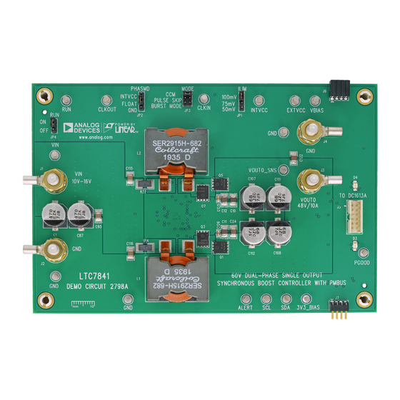
BOARD PHOTO
60V Dual-Phase Single Output Synchronous
IN
Figure 1. Single-Output LTC7841/DC2798A Demo Circuit
DEMO MANUAL DC2798A
Boost Controller with PMBus
software LTpowerPlay
SMBus/PMBus dongle DC1613A to connect to the board.
to 48V.
LTpowerPlay allows the user to reconfigure the part on-
the-fly, view telemetry of voltage, current, temperature
and fault status.
GUI Download
The software can be downloaded from:
LTpowerPlay
For more details and instructions of LTpowerPlay, please
refer to LTpowerPlay GUI for LTC7841 Quick Start Guide.
Design files for this circuit board are
All registered trademarks and trademarks are the property of their respective owners.
LTC7841
onto your PC and use ADI's I
®
available.
2
C/
Rev. 0
1
Advertisement

Subscribe to Our Youtube Channel
Related Manuals for Analog Devices Linear ADI Power DC2798A


Summary of Contents for Analog Devices Linear ADI Power DC2798A
- Page 1 DEMO MANUAL DC2798A LTC7841 60V Dual-Phase Single Output Synchronous Boost Controller with PMBus DESCRIPTION Demonstration circuit 2798A is a high voltage, dual-phase software LTpowerPlay onto your PC and use ADI’s I ® single output boost converter with 10V to 16V input SMBus/PMBus dongle DC1613A to connect to the board.
-
Page 2: Quick Start Procedure
DEMO MANUAL DC2798A PERFORMANCE SUMMARY Specifications are at T = 25°C PARAMETER CONDITIONS UNITS Input Voltage Range Output Voltage, V = 10V to 16V, I = 0A to 10A 48 (Default) Maximum Output Current, I = 10V to 16V, V = 16V to 48V Typical Efficiency =12V, V... - Page 3 DEMO MANUAL DC2798A QUICK START PROCEDURE – Figure 3. Measuring Output Voltage Ripple Connecting a PC to DC2798A set points, ON/OFF control. The DC1613A dongle may be plugged when V is present. You can use a PC to configure the power management features of the LTC7841 such as: nominal V , margin Figure 4.
- Page 4 DEMO MANUAL DC2798A QUICK START PROCEDURE LOAD CURRENT (A) dc2798a F05 Figure 5. Efficiency vs Load Current at V = 12V, f = 150kHz, V = 48V 20MHz BW 100mV/DIV 20MHz BW 200mV/DIV 0A TO 2.5A LOAD STEP dc2798A F06 dc2798A F07 200 s/DIV 5 s/DIV Figure 6.
- Page 5 You can use LTpowerPlay to evaluate and documentation. The LTpowerPlay software can be Analog Devices ICs by connecting to a demo board sys- downloaded from: tem. LTpowerPlay provides unprecedented diagnostic and LTpowerPlay debug features.
- Page 6 DEMO MANUAL DC2798A LTPOWERPLAY QUICK START PROCEDURE The following procedure describes how to use LTpowerPlay c. Writing to the MFR_VOUT_COMMAND register via the to monitor and change the settings of LTC7841. PMBus allows the adjustment of the V reference from 0% to 100% of the maximum reference of 2.4V. 1.
- Page 7 DEMO MANUAL DC2798A LTPOWERPLAY QUICK START PROCEDURE d. If you want to set the output voltage to be 24V. In the f. In the popup “Apply an operation to all devices” dialog Config tab, type in 50 in the MFR_VOUT_COMMAND_ box, click the “On”...
- Page 8 RES., 191k, 1%, 1/10W, 0603 VISHAY, CRCW0603191KFKEA R200 RES., 30k, 1%, 1/10W, 0603, AEC-Q200 KOA SPEER, RK73H1JTTD3002F R201 RES., 38.3k, 1%, 1/10W, 0603, AEC-Q200 NIC, NRC06F3832TRF R202 RES., 150k, 1%, 1/10W, 0603 PANASONIC, ERJ3EKF1503V IC, POWER CONTROLLER, QFN-36 (5x6) ANALOG DEVICES., LTC7841EUHE#PBF Rev. 0...
-
Page 9: Parts List
TEST POINT, TURRET, 0.094" MTG. HOLE, PCB 0.062" THK MILL-MAX, 2501-2-00-80-00-00-07-0 E40, E42, E44 J1-J4 EVAL BOARD STUD HARDWARE SET, #10-32 ANALOG DEVICES, 720-0010 CONN., HDR, SHROUDED, MALE, 2×6, 2mm, VERT, ST, THT FCI, 98414-G06-12ULF CONN., HDR, FEMALE, 2×4, 2mm, R/A THT SULLINS CONNECTOR SOLUTIONS, NPPN042FJFN-RC CONN., HDR, MALE, 2×4, 2mm, R/A THT... - Page 10 DEMO MANUAL DC2798A SCHEMATIC DIAGRAM Rev. 0...
-
Page 11: Schematic Diagram
Devices for its use, nor for any infringements of patents or other rights of third parties that may result from its use. Specifications subject to change without notice. No license is granted by implication or otherwise under any patent or patent rights of Analog Devices. - Page 12 Board until you have read and agreed to the Agreement. Your use of the Evaluation Board shall signify your acceptance of the Agreement. This Agreement is made by and between you (“Customer”) and Analog Devices, Inc. (“ADI”), with its principal place of business at One Technology Way, Norwood, MA 02062, USA. Subject to the terms and conditions of the Agreement, ADI hereby grants to Customer a free, limited, personal, temporary, non-exclusive, non-sublicensable, non-transferable license to use the Evaluation Board FOR EVALUATION PURPOSES ONLY.
Need help?
Do you have a question about the Linear ADI Power DC2798A and is the answer not in the manual?
Questions and answers