Advertisement
Quick Links
DESCRIPTION
Demonstration circuit 2784B-A is a high efficiency, high
density, µModule
regulator with 4.5V to 16V input range.
®
The output voltage is adjustable from 0.5V to 1.8V and it
can supply 200A maximum load current. The demo board
has two
LTM
4700
µModule regulators, which is a dual
®
50A or single 100A step-down regulator with digital power
system management. See LTM4700 data sheet for more
detailed information.
The DC2784B-A powers up to default settings and pro-
duces power based on configuration resistors without
the need for any serial bus communication. This allows
easy evaluation of the DC/DC converter. To fully explore
the extensive power system management features of
the part, download the graphical user interface (GUI)
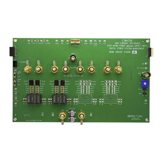
BOARD PHOTO
High Current, PolyPhase
Power µModule Supply with Digital Power
System Management 2 × LTM4700, 200A
Part marking is either ink mark or laser mark
Figure 1. 2 × LTM4700; 200A DC2784B-A Demo Circuit
DEMO MANUAL
software LTpowerPlay
®
2
Devices I
C/SMBus/PMBus dongle
to the board. The LTpowerPlay allows the user to recon-
figure the part on-the-fly and store the configuration in
EEPROM, view telemetry of voltage, current, temperature,
and fault status.
GUI Download
The software can be downloaded from LTpowerPlay.
For more details and instructions of LTpowerPlay, please
refer to LTpowerPlay GUI for LTM4700 Quick Start Guide.
Design files for this circuit board are
All registered trademarks and trademarks are the property of their respective owners.
DC2784B-A
LTM4700
Step-Down
®
onto your PC and use Analog
DC1613A
to connect
available.
Rev. 0
1
Advertisement

Related Manuals for Analog Devices DC2784B-A


Summary of Contents for Analog Devices DC2784B-A
- Page 1 GUI Download detailed information. The software can be downloaded from LTpowerPlay. The DC2784B-A powers up to default settings and pro- duces power based on configuration resistors without For more details and instructions of LTpowerPlay, please the need for any serial bus communication. This allows refer to LTpowerPlay GUI for LTM4700 Quick Start Guide.
- Page 2 DEMO MANUAL DC2784B-A PERFORMANCE SUMMARY Specifications are at T = 25°C PARAMETER CONDITIONS VALUE Input Voltage Range Output Voltage, V = 4.5V to 16V, I = 0A to 200A Maximum Output Current, I = 4.5V to 16V, V = 0.5V to 1.8V...
- Page 3 DEMO MANUAL DC2784B-A QUICK START PROCEDURE – LOAD 0A TO 200A – DC2784BA F02 4.5V TO 16V – – – Figure 2. Proper Measurement Equipment Setup – Figure 3. Measuring Output Voltage Ripple Rev. 0...
- Page 4 DEMO MANUAL DC2784B-A QUICK START PROCEDURE Connecting a PC to DC2784B-A You can use a PC to reconfigure the power management sequencing parameters, the fault log, fault responses, features of the LTM4700 such as: nominal V , mar- GPIOs and other functionalities. The DC1613A dongle...
- Page 5 DEMO MANUAL DC2784B-A QUICK START PROCEDURE 1.0V 350kHz 1.5V 500kHz DC LOAD CURRENT (A) DC2784BA F05 Figure 5. Efficiency vs Load Current at V = 12V (RUNP is ON) 20MHz BW 20mV/DIV 100A TO 150A LOAD STEP 100µs/DIV DC2784BA F06 Figure 6. Output Voltage vs Load Current at V = 12V, V = 1.0V...
- Page 6 DEMO MANUAL DC2784B-A QUICK START PROCEDURE Figure 8. Thermal at V = 12V, V = 1.0V, I = 140A, T = 25°C, No Airflow Rev. 0...
- Page 7 DEMO MANUAL DC2784B-A QUICK START PROCEDURE Figure 9. Thermal at V = 12V, V = 1.0V, I = 200A, T = 25°C, 400LFM Airflow Rev. 0...
- Page 8 You can use LTpowerPlay to evaluate LTC3883’s demo system, or a customer board. The soft- Analog Devices ICs by connecting to a demo board sys- ware also provides an automatic update feature to keep tem. LTpowerPlay can also be used in an offline mode...
- Page 9 LTpowerPlay 2. Launch the LTpowerPlay GUI. a. The GUI should automatically identify the DC2784B-A. The system tree on the left hand side should look like this: Then, click the “W” (PC to RAM) icon to write these reg- ister values to the LTM4700. After finishing this step, you will see the output voltage will change to 0.8V.
- Page 10 DEMO MANUAL DC2784B-A PARTS LIST ITEM QTY REFERENCE PART DESCRIPTION MANUFACTURER/PART NUMBER Required Circuit Components CIN1, CIN16, CIN37, CIN38 CAP ., 180µF, ALUM. POLY., 25V, 20%, PANASONIC, 25SVPF180M 8mm × 12mm SMD, E12 CIN-CIN15, CIN17, CIN18 CAP ., 22µF X6S 25V 10% 1210;...
- Page 11 VISHAY, CRCW06032R00FKEA SW1, SW2 SWITCH, SUBMINIATURE SLIDE C&K COMPONENTS, JS202011CQN U1, U2 IC, LTM4700EY ANALOG DEVICES, LTM4700EY#PBF IC, MEMORY, EEPROM, 2kb (256×8), MICROCHIP , 24LC025-I/ST TSSOP-8, 400kHz IC, µPWR LDO REG W/SHUTDOWN, SO-8 ANALOG DEVICES, LT1129CS8-5#PBF IC, TIMERBLOX: VOLTAGE-CTRL. PWM,...
- Page 12 DEMO MANUAL DC2784B-A PARTS LIST ITEM QTY REFERENCE PART DESCRIPTION MANUFACTURER/PART NUMBER R230, R231 RES., OPTION, 2512 OPTION U3, U4 IC, OPT Hardware: For Demo Board Only E1-E21, E23-E26 TEST POINT, TURRET, 0.064", MTG. HOLE MILL-MAX, 2308-2-00-80-00-00-07-0 JP2, JP4 CONN., HEADER, 1×3, 2mm...
- Page 13 DEMO MANUAL DC2784B-A SCHEMATIC DIAGRAM Rev. 0...
- Page 14 DEMO MANUAL DC2784B-A SCHEMATIC DIAGRAM Rev. 0...
- Page 15 DEMO MANUAL DC2784B-A SCHEMATIC DIAGRAM Rev. 0...
- Page 16 DEMO MANUAL DC2784B-A SCHEMATIC DIAGRAM Rev. 0...
- Page 17 DEMO MANUAL DC2784B-A SCHEMATIC DIAGRAM Rev. 0...
- Page 18 DEMO MANUAL DC2784B-A SCHEMATIC DIAGRAM Rev. 0...
- Page 19 Devices for its use, nor for any infringements of patents or other rights of third parties that may result from its use. Specifications subject to change without notice. No license is granted by implication or otherwise under any patent or patent rights of Analog Devices.
- Page 20 Board until you have read and agreed to the Agreement. Your use of the Evaluation Board shall signify your acceptance of the Agreement. This Agreement is made by and between you (“Customer”) and Analog Devices, Inc. (“ADI”), with its principal place of business at One Technology Way, Norwood, MA 02062, USA. Subject to the terms and conditions of the Agreement, ADI hereby grants to Customer a free, limited, personal, temporary, non-exclusive, non-sublicensable, non-transferable license to use the Evaluation Board FOR EVALUATION PURPOSES ONLY.
Need help?
Do you have a question about the DC2784B-A and is the answer not in the manual?
Questions and answers