Advertisement
Quick Links
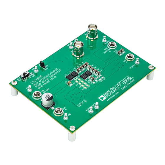
DESCRIPTION
Demonstration circuit 2543B is a high efficiency, high
density, open loop charge pump (inductorless) DC/DC
converter. This demo board is a voltage divider which
achieves a 2:1 step-down ratio from an input voltage from
36V to 60V. The output voltage is a fixed ratio of half of the
input voltage (V
/2) and can supply a 10A load current.
IN
This demo board has the option to deliver a 20A maximum
load with the addition of 15 chip capacitors. See Figure 8
and Figure 10 for the details.
The DC2543B provides a very high efficiency solution of
98.7% when converting 48V
in Figure 3. When configured for a 20A output, an effi-
ciency of up to 98.4% is achievable for a 48V
at 20A as shown in Figure 8.
The demo board features the
voltage high power switched capacitor/charge pump
controller in a 4mm × 5mm QFN package. Please see
LTC7820 data sheet for more detailed information.
PERFORMANCE SUMMARY
PARAMETER
Input Voltage Range
Output Voltage, V
OUT
Maximum Output Current, I
OUT
Typical Efficiency
Peak Efficiency
Switching Frequency
NOTE: DC2543B demo manual includes a Schottky diode added across the output. This manual describes the demo
board entitled "Demo Circuit 2543B." The DC2543B replaces the DC2543A.
to 24V
at 10A as shown
IN
OUT
to 24V
IN
LTC
7820, a fixed ratio high
®
Specifications are at T
CONDITION
V
= 36 to 60V, I
= 0A to 10A
IN
OUT
V
= 36 to 60V, V
IN
OUT
V
= 48V, V
= 24V, I
IN
OUT
V
= 48V, V
= 24V
IN
OUT
DEMO MANUAL DC2543B
High Efficiency, Charge Pump
The DC2543B needs to be powered on with no load cur-
rent or a very small load current (less than 50mA) with
the default setup. Large load current can be applied after
V
is established. The board offers a disconnect FET
O
option which is controlled by the LTC7820 FAULT pin
to disconnect the load during startup as shown in the
schematic. Please refer to "Voltage Divider Prebalance
Before Switching" section in the LTC7820 data sheet for
more details regarding the startup of the voltage divider.
The board also features some protection functions
such as overcurrent and thermal shutdown to make it a
reliable solution.
Design files for this circuit board are available at
OUT
http://www.analog.com/DC2543B
All registered trademarks and trademarks are the property of their respective owners.
= 25°C
A
= V
/2
IN
= 10A
OUT
LTC7820EUFD
DC/DC Converter
VALUE
36V to 60V
V
/ 2
IN
10A
98.7%
99%
200kHz
Rev. 0
1
Advertisement

Subscribe to Our Youtube Channel
Related Manuals for Analog Devices Linear DC2543B


Summary of Contents for Analog Devices Linear DC2543B
- Page 1 DEMO MANUAL DC2543B LTC7820EUFD High Efficiency, Charge Pump DC/DC Converter DESCRIPTION Demonstration circuit 2543B is a high efficiency, high The DC2543B needs to be powered on with no load cur- density, open loop charge pump (inductorless) DC/DC rent or a very small load current (less than 50mA) with converter.
- Page 2 DEMO MANUAL DC2543B QUICK START PROCEDURE Demonstration circuit 2543B is easy to set up to evaluate Notes: the performance of the LTC7820. Refer to Figure 1 for 1. When measuring the output or input voltage ripple, the proper measurement equipment setup and follow the do not use the long ground lead on the oscilloscope procedure below.
-
Page 3: Quick Start Procedure
DEMO MANUAL DC2543B QUICK START PROCEDURE – – – LOAD – – 36V to 60V DC2543B F01 Figure 1. Proper Measurement Equipment Setup Note: It is recommended to set the electronic load in CR (constant resistance) mode for evaluation of the DC2543B board. Some electronic loads draw negative current in CC (constant current) mode when evaluating the output overcurrent protection feature of DC2543B, which can violate the absolute maximum voltage rating –0.3V for V pin. - Page 4 DEMO MANUAL DC2543B QUICK START PROCEDURE 24.6 24.4 24.2 24.0 23.8 23.6 23.4 23.2 23.0 OUTPUT LOAD CURRENT (A) OUTPUT LOAD CURRENT (A) DC2543B F04 DC2543B F03 Figure 3. Efficiency vs Load Current at V = 48V, Figure 4. Load Regulation for 10A Design = 24V, f = 200kHz at V...
- Page 5 DEMO MANUAL DC2543B QUICK START PROCEDURE 24.6 24.4 24.2 24.0 23.8 23.6 23.4 23.2 23.0 16 18 20 16 18 20 OUTPUT LOAD CURRENT (A) OUTPUT LOAD CURRENT (A) DC2543B F08 DC2543B F09 Figure 8. Efficiency vs Load Current at V = 48V, Figure 9.
- Page 6 RES, 0603 20kΩ 5% VISHAY CRCW060320K0JNEA RES, 0603 80.6kΩ 1% YAGEO RC0603FR-0780K6L RES. 2010 1Ω 1% 1W IRC LRC-LR2010-01-1R00-F RES, 0603 100Ω 5% VISHAY CRCW0603100R0JNEA IC, LTC7820EUFD, QFN 4mm × 5mm ANALOG DEVICES, ALTC7820EUFD#PBF IC, LTC3630AEMSE ANALOG DEVICES, LTC3630EMSE#PBF Rev. 0...
-
Page 7: Parts List
DEMO MANUAL DC2543B PARTS LIST Additional Demo Board Circuit Components C10-C14, C16, C33, C34, C35, C36, CAPACITOR, OPT C60-C64, C51, C77 C30-C32, C22-C25, C69-C72, C127 Q2, Q4, Q5,Q8 OPT MOSFET, OPT R6, R19, R2, R36, R8, R11, R12, RESISTOR, OPT R20, R34, R35, R60 Hardware: For Demo Board Only E1, E2, E6-E8, E10, E12, E14, E15... - Page 8 DEMO MANUAL DC2543B SCHEMATIC DIAGRAM Rev. 0...
-
Page 9: Schematic Diagram
Devices for its use, nor for any infringements of patents or other rights of third parties that may result from its use. Specifications subject to change without notice. No license is granted by implication or otherwise under any patent or patent rights of Analog Devices. - Page 10 Board until you have read and agreed to the Agreement. Your use of the Evaluation Board shall signify your acceptance of the Agreement. This Agreement is made by and between you (“Customer”) and Analog Devices, Inc. (“ADI”), with its principal place of business at One Technology Way, Norwood, MA 02062, USA. Subject to the terms and conditions of the Agreement, ADI hereby grants to Customer a free, limited, personal, temporary, non-exclusive, non-sublicensable, non-transferable license to use the Evaluation Board FOR EVALUATION PURPOSES ONLY.
Need help?
Do you have a question about the Linear DC2543B and is the answer not in the manual?
Questions and answers