Table of Contents
Advertisement
Quick Links
DESCRIPTION
Demonstration circuit DC2510A is a shield board for use
with the DC2321A Dust
®
board is designed to allow users to build their own custom
application circuits directly on the DC2321A with access
to all pins of the
LTP5901-IPM
The board offers footprints of common sensor and IC
packages as well as prototyping space for routing. The
following footprints are included on the board:
TOP
MSSOP-10 (×2)
n
TS8 (×2)
n
SOIC-20 (×2)
n
DFN-20 (×2)
n
Power rails and grids of copper pads (in both 2mm and
2.54mm pitch) form a solderable breadboard, and the IC
footprints allow easy mounting of surface-mount packages.
Each pin on the footprints and headers also connects to
a copper-plated hole for easy wiring.
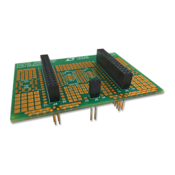
BOARD PHOTO
application demo board. This
Dust mote.
BOTTOM
SOT-23 (×4)
n
TSOT-23-8 (×2)
n
SSOP-20 (×2)
n
Figure 1. DC2510A
Shield Board for Use with
DC2321A Dust Demo Board
The headers on the board are designed to fit into the
LTP5901-IPM header layout on the DC2321A. The long
pins of the headers allow wiring below the board and give
users a place to clip grabber leads.
The headers are also stackable, allowing multiple DC2510A
boards to be connected vertically, all with access to the
pins on the DC2321A. This allows a user to create different
applications on multiple DC2510A boards and swap them
out or combine them as desired.
Please refer to the DC2321A demo manual and
LTP5901-IPM data sheet for operation information and
input limits. The application section of this demo manual
describes the system level functionality of this board and
the various ways it can be used in early design prototyping.
Design files for this circuit board are available at
http://www.linear.com/demo/DC2510A
L, LT, LTC, LTM, Linear Technology, the Linear logo and Dust are registered trademarks of
Analog Devices, Inc. All other trademarks are the property of their respective owners.
DEMO MANUAL
DC2510A
dc2510afa
1
Advertisement
Table of Contents

Subscribe to Our Youtube Channel
Related Manuals for Analog Devices DC2510A


Summary of Contents for Analog Devices DC2510A
- Page 1 Each pin on the footprints and headers also connects to L, LT, LTC, LTM, Linear Technology, the Linear logo and Dust are registered trademarks of a copper-plated hole for easy wiring. Analog Devices, Inc. All other trademarks are the property of their respective owners. BOARD PHOTO Figure 1. DC2510A...
-
Page 2: Absolute Maximum Ratings
DEMO MANUAL DC2510A ABSOLUTE MAXIMUM RATINGS Supply Voltage on VSUPPLY ..........................4.20V Input Voltage on ADC Inputs ..........................1.98V Voltage on Any Digital I/O Pin ....................–0.3V to VSUPPLY + 0.3V SPECIFICATIONS TYPICAL/ PIN TYPE PARAMETER DEFAULT UNITS Power VSUPPLY 3.76 ADCs... - Page 3 DEMO MANUAL DC2510A SPECIFICATIONS Figure 3. DC2510A Top Assembly Drawing dc2510afa...
- Page 4 DEMO MANUAL DC2510A SPECIFICATIONS Figure 4. DC2510A Bottom Assembly Drawing dc2510afa...
-
Page 5: Quick Start Procedure
QUICK START PROCEDURE Instructions Combining Application Circuits To use DC2510A, you will need to connect a sensor to the Because DC2510A is stackable, a user can make custom board. This device can be soldered onto the grid of copper applications on several different boards and connect all pads, attached to one of the provided SMD footprints, or of the boards together to combine the circuits. - Page 6 DEMO MANUAL DC2510A QUICK START PROCEDURE Table 1. Inputs and Interfaces Key Pin Type Pin Function Readable Though GUI Notes – – 5VUSB – Power 3V3USB – VSUPPLY Abs Max is 4.20V UART – Serial – Communication Remove R1 on DC2321A to Free SS Full-Scale Voltage is 1.8V, Abs Max is 1.98V...
-
Page 7: Parts List
DEMO MANUAL DC2510A PARTS LIST ITEM REFERENCE PART DESCRIPTION MANUFACTURER/PART NUMBER Required Circuit Components J4, J6 2×16, 2mm PITCH, VERTICAL STACKABLE SOCKET SAMTEC, ESQT-116-02-GF-D-310 2 PIN, 2mm PITCH, VERTICAL STACKABLE SOCKET SAMTEC, ESQT-102-02-GF-S-310 FAB, PRINTED CIRCUIT BOARD DEMO CIRCUIT 2510A-1... -
Page 8: Schematic Diagram
DEMO MANUAL DC2510A SCHEMATIC DIAGRAM dc2510afa... - Page 9 DEMO MANUAL DC2510A SCHEMATIC DIAGRAM dc2510afa Information furnished by Linear Technology Corporation is believed to be accurate and reliable. However, no responsibility is assumed for its use. Linear Technology Corporation makes no representa- tion that the interconnection of its circuits as described herein will not infringe on existing patent rights.
- Page 10 DEMO MANUAL DC2510A DEMONSTRATION BOARD IMPORTANT NOTICE Linear Technology Corporation (LTC) provides the enclosed product(s) under the following AS IS conditions: This demonstration board (DEMO BOARD) kit being sold or provided by Linear Technology is intended for use for ENGINEERING DEVELOPMENT OR EVALUATION PURPOSES ONLY and is not provided by LTC for commercial use.
- Page 11 Mouser Electronics Authorized Distributor Click to View Pricing, Inventory, Delivery & Lifecycle Information: Analog Devices Inc. DC2510A...
Need help?
Do you have a question about the DC2510A and is the answer not in the manual?
Questions and answers