Advertisement
Quick Links
DESCRIPTION
Demonstration circuit 2702B-B is a single output, dual-
phase, high efficiency, high density, µModule
with a 4.5V to 16V input range. The output voltage is
adjustable from 0.5V to 1.8V and can supply 100A maxi-
mum load current. The DC2702B-B demo board has a
LTM
4700
µModule regulator, a dual 50A or single 100A
®
step-down regulator with digital power system man-
agement. Refer to the LTM4700 data sheet for more
detailed information.
DC2702B-B powers up to default settings and produces
power based on configuration resistors without serial bus
communication. This feature allows easy evaluation of
the DC/DC converter. To fully explore the extensive power
system management features of the LTM4700, download
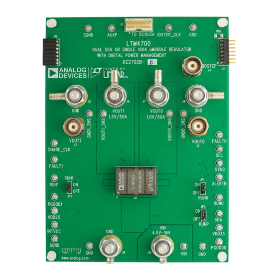
BOARD PHOTO
Single 100A µModule Regulator with
Digital Power System Management
regulator
®
Part marking is either ink mark or laser mark
Figure 1. Single Output LTM4700/DC2702B-B Demo Circuit
DEMO MANUAL DC2702B-B
the GUI software LTpowerPlay
2
Analog Devices I
C/SMBus/PMBus dongle
connect to the board. LTpowerPlay allows the user to
reconfigure the part on-the-fly, store the configuration in
EEPROM, view telemetry of voltage, current, temperature
and fault status.
Graphic User Interface (GUI) Download
The software can be downloaded from LTpowerPlay.
For more details and instructions on LTpowerPlay, refer to
LTpowerPlay GUI for LTM4700 Quick Start Guide.
Design files for this circuit board are
All registered trademarks and trademarks are the property of their respective owners.
LTM4700
onto your PC and use
®
DC1613A
to
available.
Rev. 0
1
Advertisement

Related Manuals for Analog Devices DC2702B-B


Summary of Contents for Analog Devices DC2702B-B
- Page 1 LTpowerPlay allows the user to adjustable from 0.5V to 1.8V and can supply 100A maxi- reconfigure the part on-the-fly, store the configuration in mum load current. The DC2702B-B demo board has a EEPROM, view telemetry of voltage, current, temperature 4700 µModule regulator, a dual 50A or single 100A...
-
Page 2: Performance Summary
DEMO MANUAL DC2702B-B PERFORMANCE SUMMARY Specifications are at T = 25°C PARAMETER CONDITIONS UNITS Input Voltage Range Output Voltage, V = 4.5V to 16V, I = 0A to 100A OUT0 OUT0 Maximum Output Current, I = 4.5V to 16V, V = 0.5V to 1.8V... - Page 3 DEMO MANUAL DC2702B-B QUICK START PROCEDURE Figure 2. Proper Measurement Equipment Setup – Figure 3. Measuring Output Voltage Ripple DC2702B-B F03 Rev. 0...
- Page 4 DEMO MANUAL DC2702B-B QUICK START PROCEDURE Connecting a PC to DC2702B-B as nominal V , margin set points, OV/UV limits, tem- perature fault limits, sequencing parameters, the fault A Personal Computer (PC) can be used to reconfigure log, fault responses, GPIOs and other functionalities. The the power management features of the LTM4700, such...
- Page 5 DEMO MANUAL DC2702B-B QUICK START PROCEDURE OUT0 (20MHz BW) 20mV/DIV LOAD STEP 50A TO 75A/DIV DC2702B-B F06 Figure 6. Output Voltage V vs Load Current (V = 1.0V) OUT0 OUT0 OUT0 (20MHz BW) 5mV/DIV DC2702B-B F07 Figure 7. Output Voltage Ripple at V = 12V, V = 1.0V, I...
- Page 6 You can use LTpowerPlay to evalu- demo system, or a customer board. The software also ate Analog Devices ICs by connecting to a demo board provides an automatic update feature to keep the software system. LTpowerPlay can also be used in an offline mode...
- Page 7 2. Launch the LTpowerPlay GUI. a. The GUI should automatically identify the DC2702B-B. The system tree on the left-hand side should look like as shown in the following figure: e. Then, click the “W” (PC to RAM) icon to write these register values to the LTM4700.
- Page 8 DEMO MANUAL DC2702B-B PARTS LIST ITEM REFERENCE PART DESCRIPTION MANUFACTURER/PART NUMBER Required Circuit Components COUT1-COUT10, COUT14-COUT16, CAP ., 330μF, X6S, 4V, 20%, 1210 TAIYO YUDEN, AMK325AC6337MM-P COUT18-COUT22 CIN1 CAP ., 180μF, ALUM. POLY., 25V, 20%, PANASONIC, 25SVPF180M 8mm × 12mm SMD, E12 CAP ., 6800pF, X7R, 50V, 5%, 0603...
-
Page 9: Parts List
DEMO MANUAL DC2702B-B PARTS LIST ITEM REFERENCE PART DESCRIPTION MANUFACTURER/PART NUMBER Additional Demo Board Circuit Components C1, C2, C14, C16, C17, C29, C31, C32 CAP ., OPTION, 0603 D1, D2 DIODE, OPTION, SOD-323 R3, R8, R26, R27, R61, R62, R64, R67, RES., OPTION, 0603... - Page 10 DEMO MANUAL DC2702B-B SCHEMATIC DIAGRAM Rev. 0...
- Page 11 DEMO MANUAL DC2702B-B SCHEMATIC DIAGRAM Rev. 0...
- Page 12 DEMO MANUAL DC2702B-B SCHEMATIC DIAGRAM Rev. 0...
-
Page 13: Revision History
Devices for its use, nor for any infringements of patents or other rights of third parties that may result from its use. Specifications subject to change without notice. No license is granted by implication or otherwise under any patent or patent rights of Analog Devices. - Page 14 Board until you have read and agreed to the Agreement. Your use of the Evaluation Board shall signify your acceptance of the Agreement. This Agreement is made by and between you (“Customer”) and Analog Devices, Inc. (“ADI”), with its principal place of business at One Technology Way, Norwood, MA 02062, USA. Subject to the terms and conditions of the Agreement, ADI hereby grants to Customer a free, limited, personal, temporary, non-exclusive, non-sublicensable, non-transferable license to use the Evaluation Board FOR EVALUATION PURPOSES ONLY.
Need help?
Do you have a question about the DC2702B-B and is the answer not in the manual?
Questions and answers