Advertisement
Quick Links
Regulator with Digital Power System Management
DESCRIPTION
Demonstration circuit 2863A features the
which is a dual 30A or single 60A µModule
with a 4.5V to 16V input range. Two LTM4680 µModule
ICs are paralleled on this board to deliver 120A maximum
load current. The output voltage is adjustable from 0.5V to
3.3V. Refer to the LTM4680 data sheet for more detailed
information.
The DC2863A powers up to default settings and pro-
duces power based on configuration resistors without
the need for any serial bus communication. This allows
easy evaluation of the DC/DC converter. To fully explore
the extensive power system management features of the
LTM4680, download the GUI software LTpowerPlay
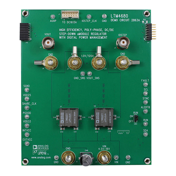
BOARD PHOTO
High Efficiency, PolyPhase 120A µModule
LTM
4680,
®
regulator
®
onto
®
Part marking is either ink mark or laser mark
Figure 1. LTM4680/DC2863A Demo Circuit
DEMO MANUAL DC2863A
2
your PC and use ADI I
C/SMBus/PMBus dongle
to connect to the board. LTpowerPlay allows the user to
reconfigure the part on-the-fly and store the configuration
in EEPROM, view telemetry of voltage, current, tempera-
ture and fault status.
GUI Download
The software can be downloaded from LTpowerPlay.
For more details and instructions on LTpowerPlay, Refer
to the LTpowerPlay GUI for LTM4680 quick start guide.
Design files for this circuit board are
All registered trademarks and trademarks are the property of their respective owners.
LTM4680
DC1613A
available.
Rev. 0
1
Advertisement

Subscribe to Our Youtube Channel
Related Manuals for Analog Devices DC2863A


Summary of Contents for Analog Devices DC2863A
- Page 1 GUI Download information. The software can be downloaded from LTpowerPlay. The DC2863A powers up to default settings and pro- duces power based on configuration resistors without For more details and instructions on LTpowerPlay, Refer the need for any serial bus communication. This allows to the LTpowerPlay GUI for LTM4680 quick start guide.
-
Page 2: Performance Summary
DEMO MANUAL DC2863A PERFORMANCE SUMMARY Specifications are at T = 25°C PARAMETER CONDITIONS UNITS Input Voltage Range Output Voltage, V = 4.5V to 16V, I = 0A to 120A Maximum Output Current, I = 4.5V to 16V, V = 0.5V to 3.3V... - Page 3 DEMO MANUAL DC2863A QUICK START PROCEDURE Figure 2. Proper Measurement Equipment Setup – Figure 3. Measuring Output Voltage Ripple Rev. 0...
- Page 4 DEMO MANUAL DC2863A QUICK START PROCEDURE Connecting a PC to DC2863A OV/UV limits, temperature fault limits, sequencing param- eters, the fault log, fault responses, GPIOs and other func- Use a PC to reconfigure the power management features tionalities. The DC1613A dongle may be plugged in when...
-
Page 5: Typical Performance Characteristics
DEMO MANUAL DC2863A TYPICAL PERFORMANCE CHARACTERISTICS = 5V = 9V = 12V = 15V 12 24 36 48 60 72 84 96 108 120 LOAD CURRENT (A) dc2863a F05 Figure 5. Efficiency vs Load Current, V = 1V, f = 500kHz... - Page 6 DEMO MANUAL DC2863A TYPICAL PERFORMANCE CHARACTERISTICS (a) Front View (b) Side View Figure 8. Thermal at V = 12V, V = 1V, I = 120A, T = 25°C, No Airflow Rev. 0...
- Page 7 LTC3887. The software supports a variety of different LTC3887’s demo system, or a customer board. The soft- tasks. You can use LTpowerPlay to evaluate Analog Devices ware also provides an automatic update feature to keep ICs by connecting to a demo board system. LTpowerPlay...
- Page 8 1. Download and install the LTpowerPlay GUI. 2. Launch the LTpowerPlay GUI. a. The GUI should automatically identify the DC2863A. The system tree on the left hand side should look like this: e. Then, click the “W” (PC to RAM) icon to write these register values to the LTM4680.
-
Page 9: Parts List
DEMO MANUAL DC2863A PARTS LIST ITEM REFERENCE PART DESCRIPTION MANUFACTURER/PART NUMBER Required Circuit Components COUT1-COUT3, COUT6-COUT8, CAP ., 100μF, X5R, 6.3V, 20%, 1210 AVX, 12106D107MAT2A COUT18, COUT19, COUT26, COUT27, C34, C35, C45, C46 CIN1, CIN6 CAP ., 330μF, ALUM POLY HYB, 35V, 20%, RADIAL,... - Page 10 DEMO MANUAL DC2863A PARTS LIST ITEM REFERENCE PART DESCRIPTION MANUFACTURER/PART NUMBER R8, R27-R31, R64, R67, R74, RES., OPTION, 0603 R75, R83, R107, R110, R128, R129, R130, R131 RES., OPTION, 1210 RES., OPTION, 1206 IC, MEMORY, EEPROM, 2kb (256 × 8),...
- Page 11 DEMO MANUAL DC2863A SCHEMATIC DIAGRAM Rev. 0...
- Page 12 DEMO MANUAL DC2863A SCHEMATIC DIAGRAM Rev. 0...
- Page 13 DEMO MANUAL DC2863A SCHEMATIC DIAGRAM Rev. 0...
- Page 14 DEMO MANUAL DC2863A SCHEMATIC DIAGRAM Rev. 0...
-
Page 15: Revision History
Devices for its use, nor for any infringements of patents or other rights of third parties that may result from its use. Specifications subject to change without notice. No license is granted by implication or otherwise under any patent or patent rights of Analog Devices. - Page 16 Board until you have read and agreed to the Agreement. Your use of the Evaluation Board shall signify your acceptance of the Agreement. This Agreement is made by and between you (“Customer”) and Analog Devices, Inc. (“ADI”), with its principal place of business at One Technology Way, Norwood, MA 02062, USA. Subject to the terms and conditions of the Agreement, ADI hereby grants to Customer a free, limited, personal, temporary, non-exclusive, non-sublicensable, non-transferable license to use the Evaluation Board FOR EVALUATION PURPOSES ONLY.
Need help?
Do you have a question about the DC2863A and is the answer not in the manual?
Questions and answers