Advertisement
Quick Links
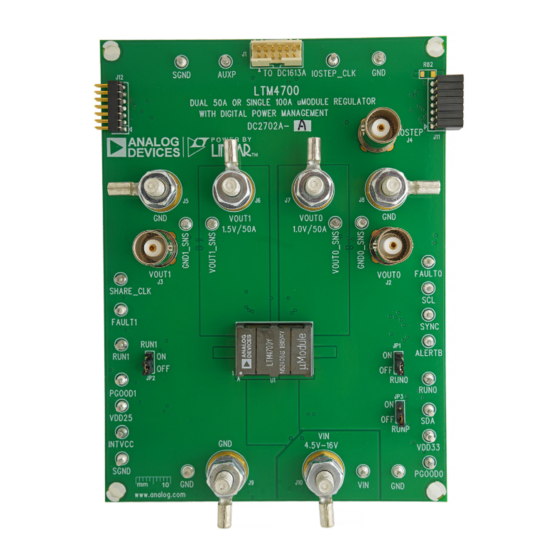
Dual 50A or Single 100A µModule Regulator
DESCRIPTION
Demonstration circuit 2702A-A is a dual-output, high
efficiency, high density, µModule regulator with 4.5V to
16V input range. Each output can supply 50A maximum
load current. The demo board has a
regulator, which is a dual 50A or single 100A step-down
regulator with digital power system management. Please
see LTM4700 data sheet for more detailed information.
DC2702A-A powers up to default settings and produce
power based on configuration resistors without the need
for any serial bus communication. This allows easy evalu-
ation of the DC/DC converter. To fully explore the extensive
power system management features of the part, down-
load the GUI software LTpowerPlay™ onto your PC and use
BOARD PHOTO
With Digital Power System Management
LTM4700
µModule
Figure 1. Dual-Output LTM4700/DC2702A-A Demo Circuit
DEMO MANUAL DC2702A-A
2
LTC's I
C/SMBus/PMBus dongle DC1613A to connect to
the board. LTpowerPlay allows the user to reconfigure the
part on the fly and store the configuration in EEPROM, view
telemetry of voltage, current, temperature and fault status.
GUI Download
The software can be downloaded from:
For more details and instructions of LTpowerPlay, please
refer to LTpowerPlay GUI for LTM4700 Quick Start Guide.
Design files for this circuit board are
All registered trademarks and trademarks are the property of their respective owners.
LTM4700EY
LTpowerPlay
available.
Rev 0
1
Advertisement

Related Manuals for Analog Devices LINEAR DC2702A-A


Summary of Contents for Analog Devices LINEAR DC2702A-A
- Page 1 DEMO MANUAL DC2702A-A LTM4700EY Dual 50A or Single 100A µModule Regulator With Digital Power System Management DESCRIPTION Demonstration circuit 2702A-A is a dual-output, high LTC’s I C/SMBus/PMBus dongle DC1613A to connect to efficiency, high density, µModule regulator with 4.5V to the board.
-
Page 2: Performance Summary
DEMO MANUAL DC2702A-A PERFORMANCE SUMMARY Specifications are at T = 25°C PARAMETER CONDITIONS VALUE Input Voltage Range 4.5V to 16V Output Voltage, V = 4.5V to 16V, I = 0A to 50A 0.5V to 1.8V, Default: 1.0V OUT0 OUT0 Maximum Output Current, I = 4.5V to 16V, V = 0.5V to 1.8V OUT0... - Page 3 DEMO MANUAL DC2702A-A QUICK START PROCEDURE – – OUT0 OUT1 LOAD0 LOAD1 0A-50A 0A-50A – – OUT0 OUT1 DC2702A F02 4.5V to 16V – – – Figure 2. Proper Measurement Equipment Setup – Figure 3. Measuring Output Voltage Ripple Rev 0...
- Page 4 DEMO MANUAL DC2702A-A QUICK START PROCEDURE Connecting a PC to DC2702A gin set points, OV/UV limits, temperature fault limits, sequencing parameters, the fault log, fault responses, You can use a PC to reconfigure the power management GPIOs and other functionalities. The DC1613A dongle features of the LTM4700 such as: nominal V , mar- may be plugged when V...
- Page 5 DEMO MANUAL DC2702A-A QUICK START PROCEDURE (20MHz BW) [50mV/DIV] OUT1 (20MHz BW) [50mV/DIV] OUT0 0A to 12.5A LOAD STEP 0A to 12.5A LOAD STEP DC2702A-A F07 DC2702A-A F08 Figure 7. Output Voltage V vs Load Current (V = 1.0V) Figure 8. Output voltage V vs Load Current (V = 1.5V) OUT0...
- Page 6 DEMO MANUAL DC2702A-A QUICK START PROCEDURE Figure 11. Thermal at V = 12V, V = 1.0V, I = 50A, V = 1.5V, I = 50A, T = 25°C, No Airflow OUT0 OUT0 OUT1 OUT1 Figure 12. Thermal at V = 12V, V = 1.0V, I = 50A, V = 1.5V, I...
- Page 7 DEMO MANUAL DC2702A-A LTPOWERPLAY SOFTWARE GUI LTpowerPlay is a powerful Windows based development DC1613A USB-to-SMBus controller to communicate with environment that supports Linear Technology power one of many potential targets, including the LTM4675, system management ICs and μModules, including the LTM4676, LTM4677, LTM4678, LTC3880, LTC3882, LTM4675, LTM4676, LTM4677, LTM4678, LTC3880, LTC3883’s demo system, or a customer board.
- Page 8 DEMO MANUAL DC2702A-A LTPOWERPLAY QUICK START PROCEDURE The following procedure describes how to use LTpowerPlay to monitor and change the settings of LTM4700. 1. Download and install the LTpowerPlay GUI. 2. Launch the LTpowerPlay GUI. a. The GUI should automatically identify the DC2702A. The system tree on the left hand side should look like this: Then, click the “W”...
-
Page 9: Parts List
DEMO MANUAL DC2702A-A PARTS LIST ITEM REFERENCE PART DESCRIPTION MANUFACTURER/PART NUMBER Required Circuit Components COUT1, COUT2, COUT3, COUT6, CAP ., 330µF, X6S, 4V, 20%, 1210 TAIYO YUDEN, AMK325AC6337MM-P COUT7, COUT8, COUT14, COUT15, COUT16, COUT18, COUT19, COUT20, COUT21, COUT22, COUT9, COUT10 CIN1 CAP ., 180µF, ALUM. - Page 10 NIC, NRC06F1582TRF PANASONIC, ERJ3EKF1582V VISHAY, CRCW060315K8FKEA RES 0.001Ω, 1%, 1W, 2010 VISHAY, WSL20101L000FEA18 IC, DUAL 50A POP PSM MODULE, ANALOG DEVICES, LTM4700EY#PBF BGA 15 × 22 × 7.82mm IC, MEMORY, EEPROM, 2Kb (256x8), TSSOP-8, MICROCHIP , 24LC025-I/ST 400kHz MICROCHIP , 24LC025T-I/ST XJP1, XJP2 CONN., SHUNT, FEMALE, 2 POS, 2mm...
-
Page 11: Schematic Diagram
DEMO MANUAL DC2702A-A SCHEMATIC DIAGRAM Rev 0... - Page 12 DEMO MANUAL DC2702A-A SCHEMATIC DIAGRAM Rev 0...
- Page 13 Devices for its use, nor for any infringements of patents or other rights of third parties that may result from its use. Specifications subject to change without notice. No license is granted by implication or otherwise under any patent or patent rights of Analog Devices.
- Page 14 Board until you have read and agreed to the Agreement. Your use of the Evaluation Board shall signify your acceptance of the Agreement. This Agreement is made by and between you (“Customer”) and Analog Devices, Inc. (“ADI”), with its principal place of business at One Technology Way, Norwood, MA 02062, USA. Subject to the terms and conditions of the Agreement, ADI hereby grants to Customer a free, limited, personal, temporary, non-exclusive, non-sublicensable, non-transferable license to use the Evaluation Board FOR EVALUATION PURPOSES ONLY.
Need help?
Do you have a question about the LINEAR DC2702A-A and is the answer not in the manual?
Questions and answers