
Related Manuals for Side-Power SPR-300


Summary of Contents for Side-Power SPR-300
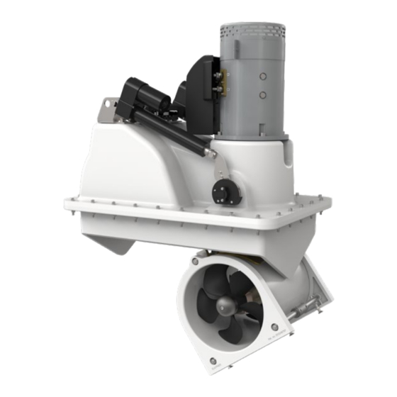
- Page 1 - 300/300 V Installation Manual SLEIPNER MOTOR AS P.O. Box 519 N-1612 Fredrikstad Norway Document id: 5927 www.side-power.com Revision: Date: 2020 © Sleipner Motor AS 2020...
-
Page 2: Table Of Contents
Contents Products Planning Installation Considerations and Precautions ....3 Thruster Measurements ............4 SRVP300/300TC - SRVP300 Vertical Retract Thruster Specifications .............. 5 Technical Specifications ............5 Positioning of the Retract Thruster ..........6 Installation Instructions Thruster Installation Considerations and Precautions ....7 Marking and Trimming of SRF Flange ........ -
Page 3: Planning Installation Considerations And Precautions
MC_0038 Planning Installation Considerations and Precautions MC_0066 • If the height of the room you are installing the Side-Power is limited consider the three diff erent confi guration designs. - Angled -Horizontal -Vertical • The thruster must NOT be installed in compartments that require ignition proof electric equipment. If necessary, make a separate compartment. -
Page 4: Thruster Measurements
MG_0179 Thruster Measurements MC_0163 SRV *300 Measurement Measurement description code inch SRF fl ange & motor housing length 33.19 Motor supplementary measurement (Height) 6.77 Motor housing height 17.80 SRF fl ange height 4.53 Retracted hatch supplementary measurement 17.52 Tunnel diameter 11.81 SRF fl... -
Page 5: Thruster Specifications
Thruster Specifi cations MC_0166 Description * 300 Available DC System (v) 24v & 48v Thrust 12v or 24v (kg * lbs) 350 kg * 749 lbs Thrust 10.5v or 21v (kg * lbs) 300 kg * 661 lbs Typical Boat Size (m * ft) 22m - 30m * 72ft - 100ft Propulsion System Twin Counter Rotating... -
Page 6: Positioning Of The Retract Thruster
Stern Installation Thruster moved to avoid confliction Thruster moved to avoid confliction Bow Installation WATERLINE Minimum tunnel depth Hatch opens towards the direction of travel SR 80 & 100 = 185mm SR 130 & 210 = 250mm SR 250 & 300 = 300mm MG_0121 Positioning of the Retract thruster... -
Page 7: Thruster Installation Considerations And Precautions
S-link control system without the designated and approved interface will render all warranties and responsibilities for the complete line of Side-Power products connected void and null. If you are interfacing by agreement with Sleipner and through a designated Side-Power supplied interface, you are still required to also install at least one original Side-Power control panel to enable effi... -
Page 8: Marking And Trimming Of Srf Flange
Ensure to have a minimum Mark using of 100mm space around internal surface Thrusters can be positioned outside of the thruster installation to the boat centre line, however, all have service access positioning measures must be considered Mark the centre line Ensure SRF of the hull keel flange is centred... -
Page 9: Installation Pre-Check
Controller Controller Apply silicon to corner areas (FUSE) SETTINGS 1 2 3 4 DOWN FAULT STATUS From power supply Remove wooden installation part Conflict with hatch hatch opens and hull without conflict Hatch does not close Hatch closed with with pressure pressure... -
Page 10: Required Modifications After Pre-Check
Raise SRF flange on stern end Conflict with hatch hatch opens and hull without conflict Use wedge to prop the SRF flange to required height hatch opens without conflict Hatch closed with pressure MG_0133 Required Modifi cations After Pre-check MC_0068 ! Please refer to the graphic for special considerations relating to your model ! To increase the space between the hatch and the hull the entire SRF fl... -
Page 11: Srf Flange Installation
Inside and outside moulding surfaces must be ground to remove coating/ material to achieve correct adhesion preparations for moulding. Fill all gaps with Expoxy filler or equivalent, with thruster case resting on Apply Epoxy filer or equivalent for the SRF flange. Grind and smoothen bonding between hull and SRF flange surfaces after cutting. -
Page 12: Motor House Installation
IMPORTANT Do not position support on the motor cap. MG_0122 Motor House Installation MC_0068 ! Please refer to the graphic for special considerations relating to your model ! Apply MS Polymer or equivalent on SRF fl ange top surface to seal and avoid water leakage. (NB: Ensure that glue is compatible with SRF and thruster case materials.) Place the upper thruster Housing down on the SRF fl... -
Page 13: Hatch Installation
Pin bolts with sharp Drill holes ends to punch mark the hole pattern to hatch Tap/ press to get punch marks of hole pattern Inside of hatch Countersink all 4 holes Outside of hatch Apply a layer of aluminium or duct Ensure to adjust the hatch tape on hatch bolts so they do NOT... -
Page 14: Motor To House Installation
Install the relevant motor and other electronics according to electrical instructions in the manual Bolt tightening force (4x) 33 Nm (24 lb/ft) MG_0107 Motor to House Installation MC_0068 ! Please refer to the graphic for special considerations relating to your model ! Install the motor onto the motor bracket ensuring both the couplings and the drive shafts have locked together. -
Page 15: Oil Tank Installation
20% x waterline to tunnel centre Oil tank WATERLINE Pivot shaft Oil valve MG_0131 Oil Tank Installation MC_0023 ! Please refer to the graphic for special considerations relating to your model ! Install the oil tank above the waterline by at least 20% of the distance from the waterline to the centre of the tunnel. This ensures enough overpressure for the oil in the gear leg. -
Page 16: Thruster Electrical Installation
IMPORTANT The Proportional Power Controller is a bulkhead (wall) mounted unit and must be installed in a dry and well-ventilated compartment. The unit also requires a 200mm minimum head clearance, 150mm minimum bottom clearance and a 100mm minimum clearance 200mm surrounding its remaining outer casing. -
Page 17: Electrical Specifications
Electrical Specifi cations MC_0044 SRP 300 5927 2020... -
Page 18: Control Panel Cable Installation
Retract **Setup with automatic panel main switch +12V Battery Power supply black cable yellow Automatic Main Switch w/S-link T-connector T-connector T-connector Controller Terminator 120 ohm Terminator 120 ohm 8730 Controller 6 1242 Foot Retract Switches Remote control thruster ( opt.) (opt.) optional Retract... -
Page 19: S-Link Planning & Precautions
Example of the control wiring with You need: Control Panel S-link system for boats with one 2 x 6 1327 End terminators Wiring of S-link system 3 x 6 1326 T-connectors control position and one thruster. 1 x 6 1328 Power spur 2 x 6 1320-xxM Backbone cables 2 x 6 1321-xxM Spur cables Explaining S-link... -
Page 20: Visual Wiring Diagram
Visual Wiring Diagram MG_0136 SRP 300 5927 2020... - Page 21 Visual Wiring Diagram MG_0137 SRP 300 5927 2020...
-
Page 22: Check Drive Shaft Alignment
Actuator arm and bearing Controller (FUSE) SETTINGS 1 2 3 4 DOWN FAULT STATUS Align pointer on lever arm with red mark on bearing MG_0108 Check drive shaft alignment MC_0069 IMPORTANT Before the thruster motor is operated, check the drive shaft alignment is completely straight when it reaches the end position form the control panel operation: 1) Connect power to thruster and S-link system. -
Page 23: Control Panel Installation
4x SCREWS Ø 4.5 mm Ø 4.5 mm 75.7 mm 58 mm 67 mm GASKET Ø 4.5 mm Ø 4.5 mm Ø 4.5 mm External alarm / buzzer connection (S-link) Supply + 12V / 24V DC Internal fuse / relay External alarm buzzer 12V / 24V DC - max 0,5A MG_0063... -
Page 24: Checklist For Dc And Ip Thrusters
Pre-delivery Checklist MC_0033 ..The bolts holding the gear house and motor bracket together are tightened correctly... The bolts holding the motor to its bracket are tightened correctly... All electrical connections are clean, dry and tight, and the correct cable, fuse and main switch size. -
Page 25: Spare Parts
Spare Parts MC_0024 For the most up to date documentation, we advise you to visit our website www.side-power.com for the spare parts list. Product Templates and Additional Resources MC_0024 For additional supporting documentation, we advise you to visit our website www.side-power.com... - Page 26 Notes MC_0037 ..............................................................................................................................................................................................................................................................................................................................................................................................................................................................................................................................................................................................................................................................................................................................................................................................................................................................................................................................................................................................................................................................................................................................................................................................................................................................................................................................................................................................................................................................................................................................................................................................................SRP 300 5927 2020...
- Page 27 Notes MC_0037 ..............................................................................................................................................................................................................................................................................................................................................................................................................................................................................................................................................................................................................................................................................................................................................................................................................................................................................................................................................................................................................................................................................................................................................................................................................................................................................................................................................................................................................................................................................................................................................................................................................SRP 300 5927 2020...
- Page 28 Worldwide sales and service www.side-power.com SLEIPNER MOTOR AS P.O. Box 519 N-1612 Fredrikstad Norway The information given in the document was correct at the time it was published. However, Sleipner Motor AS can not accept liability for any inaccuracies or omissions it may contain.
Need help?
Do you have a question about the SPR-300 and is the answer not in the manual?
Questions and answers