
Related Manuals for Side-Power SAC320/300-I-4-H-AC


Summary of Contents for Side-Power SAC320/300-I-4-H-AC
- Page 1 - 240/250 - 320/300 Installation Manual SLEIPNER MOTOR AS P.O. Box 519 N-1612 Fredrikstad Norway Document id: 5996 www.side-power.com Revision: Date: 2020 © Sleipner Motor AS 2020...
-
Page 2: Table Of Contents
Contents Bow Installation Instructions Products Bow Installation Considerations and Precautions ..... 3 Thruster Measurements ............ 4 - 5 SAC320/300-I-4-H - AC Thruster ø300mm 400V SAC320/300-I-2-H - AC Thruster ø300mm 230V Technical Specifications ............5 SAC320/300-I-4L-H - AC Thruster ø300mm 400V L.H. Measurements, PDC .............. -
Page 3: Bow Installation Considerations And Precautions
S-link control system without the designated and approved interface will render all warranties and responsibilities for the complete line of Side-Power products connected void and null. If you are interfacing by agreement with Sleipner and through a designated Side-Power supplied interface, you are still required to also install at least one original Side-Power control panel to enable effi... -
Page 4: Thruster Measurements
Drawing applies to part nr SAC700/412-C-2-V SAC700/412-C-4-V SAC700/412-C-4L-V Propeller or gear leg must never extend out of the tunnel Twin Propeller Tunnel centre line MG_0163 Designed by Material Type Date Drawing nr Tolerance NS-ISO 2768-1 Mathias LK 07.02.2018 SM-135981 Copyright All rights reserved Thruster Measurements Title SAC700/412-C-2-V... -
Page 5: Technical Specifications
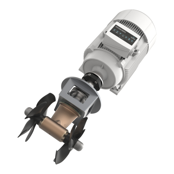
Technical Specifi cations MC_0156 Motor: AC Electric type. Gear house: Seawater resistant bronze. Gears: Hardened precision gears. Material: Seawater resistant bronze, protected with anodes. Motor bracket: Seawater resistant aluminium. Tunnel: Cross spun with rowing G.R.P tunnel Steel & aluminium tunnels available at request. Propeller: 5-blade skewback “Q-prop”... -
Page 6: Measurements, Pdc
MC_0155 42.67 104.1 104,1 Title SLEIPNER MOTOR AS Drive Controller Description © SAC Thruster / Side-Power Contents of this document is Measurements, VFD the intellectual property of Stock nr Designed by Date MC_0155 Sleipner Motor AS. It may not PDC-301 Elvira H. -
Page 7: Thruster Specifications
Thruster Specifi cations MC_0153 SAC 240 & SAC 320 5996 2020... -
Page 8: Positioning Of The Tunnel / Thruster
Pivot point important Lowered rotation power performance Stronger rotation power performance Water line Ø min 1/4 Ø (Recommended) min 1/4 Ø (Recommended) MG_0001 Positioning of the tunnel / thruster MC_0003 Aim to install the thruster as far forward as possible (1) Due to the leverage eff... -
Page 9: Tunnel Length
Do not allow the variable length of the tunnel walls to vary in length excessively. EG. the top tunnel wall is x 4 longer than the bottom wall. Water flow must have space to "straighten" itself for best Cavitation performance. -
Page 10: Tunnel Installation In Sailboats
Pos. A Pos. B MG_0004 Tunnel installation in sailboats MC_0003 Some sail boats have a fl at bottom and shallow draft in the bow section. This can make installing the thruster as far forward from the boats main pivot point diffi... -
Page 11: Water Deflection
High water force while underway High water force while underway from wave contact MG_0003 Water Defl ection MC_0003 A possible problem in sail boats or fast powerboats is that a non-rounded surface can generate drag from the back face of the tunnel, as it creates “fl at”... -
Page 12: Tunnel Ends
This “free” extra thrust in optimal installations be 30 - 40% of the total thrust. (NB: A Side-power thruster propeller does not produce cavitation at working speed. Therefore, any cavitation and cavitation noise in the tunnel will be caused during improper tunnel installation.) SAC 240 &... -
Page 13: Tunnel Installation
8 x layers of fiberglass and resin 8 x layers of fiberglass and resin MG_0005 Tunnel Installation MC_0003 IMPORTANT We recommend that a professional does the fi breglass, steel or aluminium fi tting of the tunnel. These instructions are only general instructions and do not explain in any way the details of fi... - Page 14 You must apply gel coat to areas you have grounded/ moulded to make waterproof. These areas allow water access to the hull which is typically not waterproof without these applications outside. (NB: All original Side-Power tunnels are fully waterproof when delivered except in the areas where you have cut and bonded it to the hull.)
-
Page 15: Supporting The Thruster
Fig. 2 Fig. 1 Fig. 4 Fig. 3 Fig. 6 Fig. 5 Date Drawing nr Designed by Material Type Tolerance Tore Eriksen 02.02.2012 Copyright All rights reserved Title AC Thruster Ø513 750kg SL E I PN E R M OT OR AS Fig. -
Page 16: Stern Tunnel Installation
Stern Tunnel Installation MC_0003 Stern thruster installation has extra considerations and precautions and thruster installation procedures. See the attached manual supplied in the stern thruster kit SAC 240 & SAC 320 5996 2020... -
Page 17: Thruster Installation Considerations And Precautions
S-link control system without the designated and approved interface will render all warranties and responsibilities for the complete line of Side-Power products connected void and null. If you are interfacing by agreement with Sleipner and through a designated Side-Power supplied interface, you are still required to also install at least one original Side-Power control panel to enable effi... -
Page 18: Gear Leg & Motor Bracket Installation
Boats 2 - 4 PORT STARBOARD centre line Measurement ØC Boats Description centre line inch inch Tunnel ØA 1.85 2.05 centre line 1.57 1.89 Tunnel ØC 0.43 0.43 centre line ØA Stern PORT STARBOARD Gasket Ensure propeller turns without obstruction Apply MS Polymer sealant or equal to 6 - 7... -
Page 19: Propeller Installation
DRIVE PIN PROPELLER WASHER LOCK NUT Anti-fouling ANODE Apply Loctite 243 or similar ANODE HOLDING SCREW MG_0033 Propeller Installation MC_0264 ! Please refer to the graphic for special considerations relating to your model ! Centre the drive pin and Insert the propeller onto the shaft spine. Rotate the propeller until the drive pin aligns with the internal slot in the propeller. IMPORTANT For twin counter-rotating gear legs, propellers are marked with P (Port) and S (starboard) and must be installed appropriately. -
Page 20: Coupling Installation
IMPORTANT Only use original bolts delivered with the Side-Power thruster. Also, avoid contact between the AC motor shaft and the coupling drive shaft. Centa has applied retention Inbus PlusAll glue to all bolts. (NB: The glue will harden within 4-5 hours at 20˚C.) Additional use of any loctite or anaerobic adhesives will destroy the natural vulcanisation of the rubber. -
Page 21: Motor Installation
Motor Installation MG_0168 SAC 240 & SAC 320 5996 2020... -
Page 22: Control Panel Cable Installation
Proportional Joystick Proportional Joystick Control Panel Control Panel Station 2 (opt.) Station 1 PDC 301 PDC 301 S-Link CAN control cable Power Supply S-Link 24v DC Power Supply 3 x 230v AC filter filter 3 x 400v AC (Shield) (Shield) Stern Thruster Stern Thruster MG_0169... -
Page 23: S-Link Planning & Precautions
Example of the control wiring with You need: Control Panel S-link system for boats with one 2 x 6 1327 End terminators Wiring of S-link system 3 x 6 1326 T-connectors control position and one thruster. 1 x 6 1328 Power spur 2 x 6 1320-xxM Backbone cables 2 x 6 1321-xxM Spur cables Explaining S-link... -
Page 24: Pdc 301
Confi gure the drive in Remote mode by pressing the Loc/Rem button. After being placed in Remote mode, the thruster can now operate from the Side-Power joystick panels. (NB: The PDC-301 drive controller is confi gured as a bow thruster By default. If operated as a stern thruster or in a catamaran confi guration, change the thruster instance from the setup menu of the PJC-2xx control panel.) -
Page 25: Functions And Operation
Functions and Operation MC_0158 Motor protection functions: Dynamic thrust limitation: If the electric motor winding temperature exceeds 130°C, the PDC 301 limits the maximum thrust output. The maximum thrust permitted will decrease proportionally to increasing temperatures higher than 130°C. (NB: Joystick panel will give an alert when the temperature exceeds 130°C. In this situation, the thruster can still be operated. -
Page 26: Wiring Diagram
MG_0009 SAC 240 & SAC 320 5996 2020... - Page 27 MG_0010 SAC 240 & SAC 320 5996 2020...
- Page 28 MG_0358 SAC 240 & SAC 320 5996 2020...
-
Page 29: Control Panel Installation
4x SCREWS Ø 4.5 mm Ø 4.5 mm 75.7 mm 58 mm 67 mm GASKET Ø 4.5 mm Ø 4.5 mm Ø 4.5 mm External alarm / buzzer connection (S-link) Supply + 12V / 24V DC Internal fuse / relay External alarm buzzer 12V / 24V DC - max 0,5A MG_0063... -
Page 30: Checklist For Dc And Ip Thrusters
Checklist for AC Thrusters MC_0160 ..Propeller is fastened correctly to the shaft... Propeller turns freely in tunnel... Lower-unit is fi lled with gear oil... Oil-drain screw is tightened and the copper seal is present... The anode holding screw is tightened well with thread glue... -
Page 31: Spare Parts
Spare Parts MC_0024 For the most up to date documentation, we advise you to visit our website www.side-power.com for the spare parts list. Product Templates and Additional Resources MC_0024 For additional supporting documentation, we advise you to visit our website www.side-power.com... - Page 32 Worldwide sales and service www.side-power.com SLEIPNER MOTOR AS P.O. Box 519 N-1612 Fredrikstad Norway The information given in the document was correct at the time it was published. However, Sleipner Motor AS can not accept liability for any inaccuracies or omissions it may contain.
Need help?
Do you have a question about the SAC320/300-I-4-H-AC and is the answer not in the manual?
Questions and answers