Table of Contents
Advertisement
Quick Links
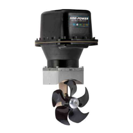
SE 60/185S IP
Ignition Protected
SIDE-POWER
thruster assembly
Thruster Systems
Installation and user manual
2175 NW 34th Ave Miami, FL 33142 USA
Phone: 786-621-3010 • Fax: 786-621-3046
Website: https://yachtaidmarine.com/product-category/marine-bow-thrusters/
Email: info@yachtaidmarine.com
https://yachtaidmarine.com/product-category/marine-bow-thrusters/
Advertisement
Table of Contents

Subscribe to Our Youtube Channel
Related Manuals for Side-Power SE 60/185S IP


Summary of Contents for Side-Power SE 60/185S IP
- Page 1 SE 60/185S IP Ignition Protected SIDE-POWER thruster assembly Thruster Systems Installation and user manual 2175 NW 34th Ave Miami, FL 33142 USA Phone: 786-621-3010 • Fax: 786-621-3046 Website: https://yachtaidmarine.com/product-category/marine-bow-thrusters/ Email: info@yachtaidmarine.com https://yachtaidmarine.com/product-category/marine-bow-thrusters/...
-
Page 2: Table Of Contents
Contents Technical specifications ............. 2 Planning & important precautions..........3 DECLARATION OF CONFORMITY Stern thruster installation considerations........3 We, Sleipner Motor AS Bolt on installation ..............4 P.O. Box 519 Mould on installation ..............5 N-1612 Fredrikstad, Norway Gearhouse and motorbracket ............ 6 declare that this product with accompanying Oil tank &... -
Page 3: Planning & Important Precautions
Planning and important precautions Prior to installation, it is important that the installer reads this guide to ensure necessary acquaintance with this product. The electromotor assembly must be handled carefully. Do not put it down on the driveshaft. Beware to keep installation within advised measurements. We advice to paint the gearhouse and propellers with antifouling. -
Page 4: Bolt On Installation
PS ! Take care with grinders as it is very easy to remove to If you are installing the standard Side-Power dual joystick much in fibreglass panel this is already secured. -
Page 5: Mould On Installation
4. Offer the stern tunnel to the desired position on the transom tery banks. and mark around the tube. If you are installing the standard Side-Power dual joystick panel this is already secured. 5. Cut the marked hole in the transom of the boat. -
Page 6: Gearhouse And Motorbracket
Fig. 1 Fig. 2 Bolt tightening forces: Bolts (2x) holding gearhouse to bracket: 17 Nm (12,4 lb/ft) Fitting gearhouse and motor bracket Fitting gearhouse and motor bracket 1. Try the lower-unit in the tunnel (remove the zinc anode) first by using the gasket inside the tunnel. Try on the propeller to make sure it 1. -
Page 7: Oil Tank & Propellers
Fig. 1 Thread glue Fitting propellers 1. Turn the propeller shaft so that the drivepin (5) is in a horizontal position and ensure that it is centred in the propellershaft. 2. Push the propeller onto the shaft with the track for the drivepin in an horizontal position (same direction as you set the drivepin), all the way in. -
Page 8: Electromotor Ip Assembly
Fig. 2 Fig. 1 Fitting the electromotor IP assembly Remove the 4 bolts in the motorbracket (Fig 1). Use the enclosed template to measure that the driveshaft has come through the motorbracket with the correct height (Fig 2). Place the motor assembly gently on the motorbracket. Make sure that the drive pin in motor drive shaft fits into the corresponding grove in the gearleg shaft. -
Page 9: Electrical Installation
RED: Battery 12V or 24V Designed by Material Type Date Drawing nr Tolerance Battery & cable recommendations: NS-ISO 2768-1 R. Hansen SM-101462 30.08.2011 Copyright All rights reserved Title Model Voltage Nominal Min. battery >7m total + & - 7-14m total + & - 15-21m total + &... -
Page 10: Control Panel And Control-Leads
Pin configuration in contacts SIDEPOWER SIDEPOWER THRUSTER THRUSTER Connect round end of control adapter SLEIPNER SLEIPNER cable to the round socket on IP casing Control panel and control-leads Control panel and control-leads • You can install as many panels as you wish by using optional Y-connectors. If two or more panels are operated at the same time in •... -
Page 11: "Visual" Wiring Diagram
"Visual" wiring diagram "Visual" wiring diagram SE 60/185S ignition protected thruster assembly SP55S2i ignition protected thruster assembly version 1.4 - 2015 1.1 - 2006 https://yachtaidmarine.com/product-category/marine-bow-thrusters/... -
Page 12: Technical Wiring Diagram
Technical wiring diagram Round connector 4 pin on motor Motor housing connector Fused blue 9 red (+) inside 1A (sig -) blue (sig +) Electronic interface box 6 1232i white black (-) grey (sig +) grey (sig -) black brown Battery Fuse main... -
Page 13: Checklist
Checklist Propeller is fastened correctly to the shaft. Propeller turns freely in tunnel. The anode holding screw is tightened well with thread glue. There is a sturdy additional support under the electric motor, taking the weight load of the electromotor assembly away ... -
Page 14: Important User Precautions
Important user precautions • Ensure that you know the location of the main battery switch that disconnects the thruster from all power sources (batteries) so that the thruster can be turned off in case of a malfunction. • Always turn the main power switch off before touching any part of the thruster, as an incidental start while touching moving parts can cause serious injuries. -
Page 15: How To Use Sidepower Thrusters
To turn panel ON Turn boat to port Bow+Stern Thruster To turn panel OFF Turn boat to starboard How to use Sidepower thrusters How to use a bowthruster How to use a bowthruster 1. Turn main power switch for the bowthruster on. (Always turn off the main power switch when not onboard.) 1. -
Page 16: Maintenance
Electromotor assembly Composite 5-blade propeller for ultimate performance. Pre-filled lifetime lubricated gearhouse. Changeable anode protects gearhouse from corrosion in seawater. Fastening screw for anode Locktite Anode Propeller lock nut Washer Drivepin for propeller Maintenance » Keep the propeller and gearhouse clean from growth by painting with antifouling before every season. PS ! The anode, sealing and propeller shafts must abso-lutely not be painted. -
Page 17: Troubleshooting
Troubleshooting Before seeking assistance at the help desk of your Sidepower dealer / distributor please perform these tests and make notes of all measurements to ensure that they have as much information as possible to work on. NB! All check points and solutions must be carried out after consulting the relevant information elsewhere in this manual to under- stand how the system is intended to work. -
Page 18: Warranty Statement
Warranty statement 1. The equipment manufactured by Sleipner Motor AS (The “Warrantor”) is warranted to be free from defects in workmanship and materials under normal use and service. 2. This Warranty is in effect for of two years (Leisure Use) or one year (Commercial use) from the date of purchase by the user. Proof of purchase must be included, to establish that it is inside the warranty period. -
Page 19: Parts List
SE 60/185S IP SP 55 S2i SE 60/185S ignition protected thruster assembly version 1.4 - 2015 SP 30 S2i / SP 40 S2 i/ SP 55 S2i 3.7 - 2006 https://yachtaidmarine.com/product-category/marine-bow-thrusters/... -
Page 20: Service Centres
Worldwide sales and service 2175 NW 34th Ave Miami, FL 33142 USA Phone: 786-621-3010 • Fax: 786-621-3046 Website: https://yachtaidmarine.com/product-category/marine-bow-thrusters/ Email: info@yachtaidmarine.com https://yachtaidmarine.com/product-category/marine-bow-thrusters/...
Need help?
Do you have a question about the SE 60/185S IP and is the answer not in the manual?
Questions and answers