Table of Contents
Advertisement
Quick Links
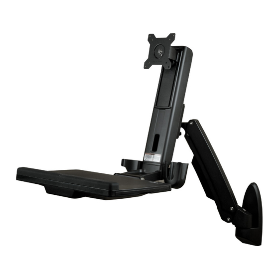
Sit-Stand Workstation Wall Mount
- Single Monitor
WALLSTS1
FR: Guide de l'utilisateur - fr.startech.com
DE: Bedienungsanleitung - de.startech.com
ES: Guía del usuario - es.startech.com
NL: Gebruiksaanwijzing - nl.startech.com
PT: Guia do usuário - pt.startech.com
IT: Guida per l'uso - it.startech.com
JP: 取扱説明書 - jp.startech.com
For the most up-to-date information, please visit: www.startech.com
Manual Revision: 04/07/2021
*actual product may vary from photos
Advertisement
Table of Contents

Related Manuals for StarTech.com STCWALLSTS1


Summary of Contents for StarTech.com STCWALLSTS1
- Page 1 DE: Bedienungsanleitung - de.startech.com ES: Guía del usuario - es.startech.com NL: Gebruiksaanwijzing - nl.startech.com PT: Guia do usuário - pt.startech.com IT: Guida per l’uso - it.startech.com JP: 取扱説明書 - jp.startech.com For the most up-to-date information, please visit: www.startech.com Manual Revision: 04/07/2021...
- Page 2 Warning statements Dichiarazioni di avvertenza Make sure that you assemble this product according to the instructions. Assicurarsi di Assemblare il prodotto secondo le istruzioni. Read the entire manual and make sure that you understand the instructions before you start to Leggere l’intero manuale e assicurarsi di aver compreso tutte le istruzioni prima di iniziare ad assemblare assemble and use this product.
- Page 3 Advertencias de uso Asegúrese de ensamblar este producto según las instrucciones. Lea todo el manual y asegúrese de haber comprendido bien las instrucciones antes de proceder con el ensamblaje y el uso de este producto. Nunca opere o ponga en funcionamiento este producto si faltan piezas o hay daños en las mismas. El uso de este producto es solo para interiores y no debe utilizarse en exteriores.
-
Page 4: Table Of Contents
Table of Contents Warnings ..............................i Product dimensions ................1 Product diagram ..................3 Technical specifications ................4 Package contents ...................6 Requirements ..................9 Assembly ....................10 Attach the wall plate to the wall ......................10 Attach the monitor arm to the wall plate ..................12 Attach the column to the keyboard tray .................. - Page 5 Clean the keyboard tray ................33 Technical support ...................34 Warranty information ................34 Instruction manual...
-
Page 6: Product Dimensions
Product dimensions 672 mm (26.4 in.) 395 mm (15.5 in.) 1073 mm (42.2 in.) 16 mm (0.6 in.) 79 mm (3.1 in.) 13 mm (0.5 in.) 50 mm (2 in.) 7 mm (0.3 in.) Instruction manual... - Page 7 956 mm (37.6 in.) 50.5 mm 369 mm to 548 mm (1.9 in.) (14.5 in. to 21.6 in.) 8 mm to 217 mm 8 mm to 217 mm 449 mm (17.7 in.) (0.3 in. to 8.5 in.) (0.3 in. to 8.5 in.) 668 mm (26.3 in.) Instruction manual...
-
Page 8: Product Diagram
100 mm (3.9 in.) 75 mm (2.9 in.) 4.5 mm (0.2 in.) 64 mm (2.5 in.) 44 mm (1.7 in.) Product diagram VESA monitor mount Column Monitor arm Wall plate Cable manager Keyboard tray Instruction manual... -
Page 9: Technical Specifications
Technical specifications Type of measurement Measurement 75 x 75 mm 100 x 100 mm VESA -5° to +35° Tilt (monitor) 0° to +90° Tilt (keyboard) 360° Pivot (monitor) +/-90° Swivel (monitor arm) Instruction manual... - Page 10 Type of measurement Measurement 24 in. or less Supported monitor size 4 to 17.6 lb. (2 to 8 kg) Supported weight (monitor) 5.5 lb. (2.5 kg) Supported weight (keyboard tray) Instruction manual...
-
Page 11: Package Contents
Package contents Monitor arm Keyboard tray Qty: One Qty: One Column Vesa monitor mount Qty: One Qty: One Wall Plate Adhesive strip Qty: One Qty: Two Instruction manual... - Page 12 Socket driver 6 mm hex key Qty: One Qty: One M6x10 mm screws M8x20 mm screw Qty: Three Qty: One Metal washer Plastic washer Qty: One Qty: One Instruction manual...
- Page 13 Mounting screws Concrete anchors Qty: Four Qty: Four 5 mm hex key M6x12 mm screws Qty: One Qty: Four M4x10 mm screws 2.5 mm hex key Qty: Four Qty: One Instruction manual...
-
Page 14: Requirements
• Monitor that is compatible with one of the VESA mounting hole patterns that WALLSTS1 supports • Pencil or pen to mark the wall • Phillips type screwdriver • ¹/₄ inch drive ratchet Requirements are subject to change. For the latest requirements, please visit www.StarTech.com/WALLSTS1. Instruction manual... -
Page 15: Assembly
Assembly Attach the wall plate to the wall Warning! Wall structures vary, and it is important to make sure that the type of structure and mounting hardware that you are using will properly support the mounted equipment. Failure to do so may result in personal injury and/or equipment damage. - Page 16 3. Position the wall plate where you want to hang the WALLSTS1 and make sure that the plate is vertical. 4. Use the four mounting holes in the wall plate as a template and mark the wall. 5. Follow the appropriate steps for the type of wall that you’re attaching the WALLSTS1 to and attach the wall plate to the wall.
-
Page 17: Attach The Monitor Arm To The Wall Plate
Attach the monitor arm to the wall plate 1. Place the monitor arm onto the projection on the wall plate. (figure 3) figure 3 Monitor arm Wall plate Projection Instruction manual... - Page 18 2. Place the plastic washer into the joint in the monitor arm. 3. Place the metal washer onto the plastic washer. 4. Insert the M8x20 mm screw through the washers and into the joint in the monitor arm. 5. Use the 6 mm hex key to tighten the screw. (figure 4) figure 4 6 mm hex key Monitor arm...
-
Page 19: Attach The Column To The Keyboard Tray
Attach the column to the keyboard tray 1. Position the column with the cutout at the bottom half of the column. 2. Line up the assembly holes on the bottom of the column with the assembly holes between the holders on the keyboard tray. (figure 5) figure 5 Column Holder... - Page 20 3. On the underside of the keyboard tray, insert the four M6x12 mm screws through the keyboard tray and into the column. (figure 6) 4. Use the 5 mm hex key to tighten the screws in place. figure 6 5 mm hex key M6x12 mm screw Keyboard tray Instruction manual...
-
Page 21: Attach The Column To The Monitor Arm
Attach the column to the monitor arm 1. Insert one of the M6x10 mm screws into the top hole in the plate on the back of the column. (figure 7) Note: Do not tighten the M6x10 mm screw and make sure that you leave between 4 and 5 mm of space between the plate and the screw. - Page 22 2. Hook the M6x10 mm screw attached to the column into the key-shaped hole at the top of the plate on the monitor arm. (figure 8) figure 8 M6x10 mm screw Key-shaped hole Monitor arm Instruction manual...
- Page 23 3. Insert the M6x10 mm screws into the lower two holes on the plate on the monitor arm. (figure 9) 4. Use the 5 mm hex key to tighten all three of the screws. figure 9 Monitor arm M6x10 mm screw 5 mm hex key Instruction manual...
-
Page 24: Attach The Vesa Monitor Mount To A Monitor
Attach the VESA monitor mount to a monitor 1. If you want to be able to rotate your monitor 360°, use a Phillips type screwdriver to remove the screw from the VESA monitor mount. (figure 10) figure 10 VESA monitor mount Screw Screwdriver Instruction manual... - Page 25 2. Position the VESA monitor mount so that the projection on the back of the mount is pointing towards the bottom of the monitor. 3. Line up the VESA monitor mount with the mounting holes on the back of the monitor.
-
Page 26: Attach The Monitor To The Column
Attach the monitor to the column 1. Carefully hook the back of the VESA monitor mount onto the plate on the column. (figure 12) figure 12 VESA monitor mount Column Instruction manual... - Page 27 2. Insert the M6x8 mm screw through the bottom of the VESA monitor mount and into the plate on the column. 3. Use the 5 mm hex key to tighten the screw. (figure 13) figure 13 VESA monitor mount M6x8 mm screw 5 mm hex key Instruction manual...
- Page 28 4. Slide the covers onto the wall plate. (figure 14) figure 14 Cover Wall plate Cover Instruction manual...
-
Page 29: Attach The Adhesive Strip
Attach the adhesive strip 1. If necessary, cut the adhesive strip to fit the length of your keyboard. 2. Separate the two sides of the adhesive strip. 3. Remove the backing from one half of the adhesive strip and stick it to the back of your keyboard. -
Page 30: Route Cables
Route cables 1. Run your cable along the column and through the slot at the bottom of the column. 2. At the top of the cable cover, squeeze the tabs and gently pull the cable cover from the monitor arm. 3. -
Page 31: Remove The Monitor
Remove the monitor Warning: Stored energy hazard! The column contains a lift mechanism that could move up quickly when you remove the monitor from the product. Before you remove the monitor, move the monitor to the highest position. Failure to do so could result in injury or property damage. -
Page 32: Adjusting The Wallsts1
Adjusting the WALLSTS1 Adjust the tilt angle of the monitor • To increase or decrease the tilt, use the 2.5 mm hex key to adjust the screw in the top of the VESA monitor mount. (figure 18) figure 18 VESA monitor mount Adjustment screw 2.5 mm hex key Instruction manual... -
Page 33: Adjust The Tilt Angle Of The Keyboard Tray
Adjust the tilt angle of the keyboard tray • Pull up or push down on the keyboard tray to adjust it from 0 to 90°. (figure 19) figure 19 Keyboard tray Instruction manual... -
Page 34: Counterbalance The Weight Of The Monitor
Counterbalance the weight of the monitor The WALLSTS1 features a one-touch height adjustment design that enables you to easily raise or lower your monitor. To use the one-touch height adjustment feature, you need to counterbalance the weight of your monitor. •... -
Page 35: Counterbalance The Weight Of The Workstation
Counterbalance the weight of the workstation The WALLSTS1 features a one-touch height adjustment design that enables you to easily raise or lower the entire workstation, including the keyboard tray. To use the one-touch height adjustment feature, you need to counterbalance the weight of the workstation. -
Page 36: Adjust The Swivel Effort Of The Monitor Arm
Adjust the swivel effort of the monitor arm • To increase or decrease the swivel effort of the monitor arm, use the 6 mm hex key to turn the screw in the plate on the back of the column to the right or left. (figure 22) Caution! When you loosen the screw, make sure that you don’t remove the screw from the joint. -
Page 37: Extend The Keyboard Tray
Extend the keyboard tray You can adjust the keyboard tray so that it extends to the left or right. • Pull the extension to the left or right. (figure 23) figure 23 Keyboard tray Extension Extension Instruction manual... - Page 38 Clean the keyboard tray You can remove the extension and the plastic cover from the wrist rest to clean them. 1. To remove the plastic cover from the wrist rest, carefully peel it off of the keyboard tray. (figure 24) 2.
- Page 39 Limitation of liability In no event shall the liability of StarTech.com Ltd. and StarTech.com USA LLP (or their officers, directors, employees or agents) for any damages (whether direct or indirect, special, punitive, incidental, consequential, or otherwise), loss of profits, loss of business, or any pecuniary loss, arising out of or related to the use of the product exceed the actual price paid for the product.
- Page 40 StarTech.com is an ISO 9001 Registered manufacturer of connectivity and technology parts. StarTech.com was founded in 1985 and has operations in the United States, Canada, the United Kingdom and Taiwan servicing a worldwide market.
Need help?
Do you have a question about the STCWALLSTS1 and is the answer not in the manual?
Questions and answers