Table of Contents
Advertisement
Quick Links
Advertisement
Table of Contents

Subscribe to Our Youtube Channel
Related Manuals for StarTech.com WALLSTS1


Summary of Contents for StarTech.com WALLSTS1
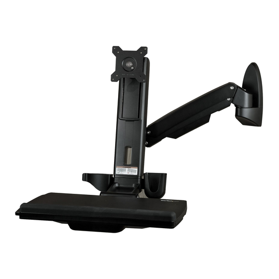
- Page 1 Sit-Stand Desk Wall Mount - Single Monitor *Actual product may vary from photos User Manual SKUs: WALLSTS1 (Black) WALL-WORKSTATION-S (Silver/White) For the latest information and specifications visit www.StarTech.com/WALLSTS1 www.StarTech.com/WALL-WORKSTATION-S Manual Revision: 01/17/2022...
- Page 2 This manual may make reference to trademarks, registered trademarks, and other protected names and/or symbols of third-party companies not related in any way to StarTech.com. Where they occur these references are for illustrative purposes only and do not represent an endorsement of a product or service by StarTech.com, or an endorsement of the product(s) to which this manual...
-
Page 3: Safety Statements
Säkerhetsåtgärder • Installation och/eller montering får endast göras av behöriga yrkespersoner och enligt gällande lokala förordningar för säkerhet och byggnormer. To view manuals, videos, drivers, downloads, technical drawings, and more visit www.startech.com/support... -
Page 4: Warning Statements
• Viktkapacitet monitorarm: 2 tilll 8 kg. • Viktkapacitet tangentbordsbricka: 2.5 kg. • Låt inte barn klättra på produkten eller använda produkten utan uppsikt. To view manuals, videos, drivers, downloads, technical drawings, and more visit www.startech.com/support... - Page 5 • Draai de schroeven niet te strak vast wanneer u dit product in elkaar zet. Als u weerstand voelt tijdens het vastdraaien van de schroeven, stop dan. To view manuals, videos, drivers, downloads, technical drawings, and more visit www.startech.com/support...
- Page 6 • キーボードトレイの耐荷重 : 2.5 kg. • 本製品に小さなお子様が乗って遊ばないようにして下さい。 お子様が使用 する際には、 適切な監視を怠らないようにして下さい。 • 本製品は、 室内での使用を想定しています。 戸外では使用しないで下さい。 • 本製品を組み立てる際、 ネジを締めすぎないようにして下さい。 ネジを締め ているうちに手応えを感じたら、 締めるのを止めてください。 • 本製品は、 二人がかりでの組み立てを想定しています。 手助けなしに単独で 組み立てと設置を行わないで下さい。 • コードやケーブルの上、 または凹凸のある床面でカートを移動させないで 下さい。 To view manuals, videos, drivers, downloads, technical drawings, and more visit www.startech.com/support...
- Page 7 • Prima di procedere allo spostamento del carrello, verificare di aver sbloccato le rotelle. To view manuals, videos, drivers, downloads, technical drawings, and more visit www.startech.com/support...
- Page 8 N’actionnez pas la poignée avant l’étape 4 de la procédure d’installation. Lorsque vous réglez la hauteur de l’écran, soutenez ou manipulez toujours l’écran avec les deux mains (comme indiqué) pour To view manuals, videos, drivers, downloads, technical drawings, and more visit www.startech.com/support...
- Page 9 Não o fazer pode resultar em danos materiais e/ou ferimentos pessoais graves. • Risco de dedos trilhados! Mantenha os dedos afastados dos componentes em movimento. To view manuals, videos, drivers, downloads, technical drawings, and more visit www.startech.com/support viii...
- Page 10 (como se muestra) para controlar con seguridad la subida o bajada de la misma. Si no lo hace, puede provocar daños materiales y/o lesiones personales graves. • ¡Peligro de Aplastamiento! Mantenga sus dedos alejados de las partes móviles. To view manuals, videos, drivers, downloads, technical drawings, and more visit www.startech.com/support...
- Page 11 Anheben oder Absenken des Displays sicher zu steuern. Andernfalls kann es zu Sachschäden und/oder schweren Personenschäden kommen. • Einklemmgefahr! Halten Sie Ihre Finger fern von beweglichen Teilen. To view manuals, videos, drivers, downloads, technical drawings, and more visit www.startech.com/support...
-
Page 12: Table Of Contents
Attach the VESA Monitor Mount to a Monitor ................13 Attach the Monitor to the Column ..................... 15 Attach the Adhesive Strip to the Keyboard ..................18 Route the Cables ............................19 To view manuals, videos, drivers, downloads, technical drawings, and more visit www.startech.com/support... - Page 13 Counterbalance the Weight of the Workstation ................25 Adjust the Monitor Swivel Tension ..................... 26 Extend the Keyboard Tray ........................27 Clean the Keyboard Tray Components ....................28 Warranty Information ................29 Limitation of Liability ................29 To view manuals, videos, drivers, downloads, technical drawings, and more visit www.startech.com/support...
-
Page 14: Product Diagram
Product Diagram Keyboard Tray Monitor Arm VESA Monitor Mount Cable Manager Column Wall Plate To view manuals, videos, drivers, downloads, technical drawings, and more visit www.startech.com/support... -
Page 15: Product Dimensions
Product Dimensions Top View 672 mm (26.4 in.) 395 mm (15.5 in.) 1073 mm (42.2 in.) Wall Plate - Side and Rear View 16 mm (0.6 in.) 79 mm (3.1 in.) 13 mm (0.5 in.) 50 mm (2 in.) 7 mm (0.3 in.) -
Page 16: Side View
8 mm to 217 mm 8 mm to 217 mm 449 mm (17.7 in.) (0.3 in. to 8.5 in.) (0.3 in. to 8.5 in.) 668 mm (26.3 in.) To view manuals, videos, drivers, downloads, technical drawings, and more visit www.startech.com/support... -
Page 17: Product Information
• Tools Pencil • Phillips Head Screwdriver x 1 • Ratchet • ¹/₄ inch Drive • To view manuals, videos, drivers, downloads, technical drawings, and more visit www.startech.com/support To view manuals, videos, drivers, downloads, technical drawings, and more visit www.startech.com/support... -
Page 18: Package Contents
Package Contents VESA Monitor Keyboard Tray Monitor Arm Column Mount Qty: 1 Qty: 1 Qty: 1 Qty: 1 M4 x 10 mm Adhesive Strip M6 x 8 mm Wall Plate Screws Screw Qty: 2 Qty: 1 Qty: 4 Qty: 1 M8 x 20 mm M6 x 12 mm Mounting Screws... -
Page 19: Installation
Failure to do so may result in personal injury and/or equipment damage. The wall should be capable of supporting at least four times the weight of the mounted equipment. To view manuals, videos, drivers, downloads, technical drawings, and more visit www.startech.com/support... -
Page 20: Attach The Wall Plate To A Wall
Place the Wall Plate onto the intended mounting location. Mark the location of the Screw Holes (x 4), using a Pencil. To view manuals, videos, drivers, downloads, technical drawings, and more visit www.startech.com/support To view manuals, videos, drivers, downloads, technical drawings, and more visit www.startech.com/support... -
Page 21: Attach The Monitor Arm To The Wall Plate
Socket. Attach the Monitor Arm to the Wall Plate 6 mm Hex Key Monitor Arm M8 x 20 mm Screw Metal Washer Plastic Washer Wall Plate Figure 2 To view manuals, videos, drivers, downloads, technical drawings, and more visit www.startech.com/support... -
Page 22: Attach The Column To The Keyboard Tray
Mounting Peg, located on the Wall Plate, and tighten, using the 6 mm Hex Key. (Figure 2) Attach the Column to the Keyboard Tray 5 mm Hex Key M6x12 mm Screw Figure 3 To view manuals, videos, drivers, downloads, technical drawings, and more visit www.startech.com/support... -
Page 23: Attach The Column To The Monitor Arm
Column. (Figure 4) Note: Do not tighten the M6 x 10 mm Screw and ensure 4 to 5 mm of space is left between the Plate and the Screw. To view manuals, videos, drivers, downloads, technical drawings, and more visit www.startech.com/support... - Page 24 Hook the M6 x 10 mm Screw, attached to the Column, into the Key-Shaped Hole, located at the top of the Plate on the Monitor Arm. (Figure 5) To view manuals, videos, drivers, downloads, technical drawings, and more visit www.startech.com/support...
- Page 25 Insert the second and third M6 x 10 mm Screws into the holes, located on the Plate on the Monitor Arm and tighten, using the 5 mm Hex Key. (Figure 6) To view manuals, videos, drivers, downloads, technical drawings, and more visit www.startech.com/support...
-
Page 26: Attach The Vesa Monitor Mount To A Monitor
Screw Screwdriver Figure 7 To enable 360 degree rotation of the Monitor, remove the Screw, located in the VESA Monitor Mount, using a Phillips Head Screwdriver. (Figure 7) To view manuals, videos, drivers, downloads, technical drawings, and more visit www.startech.com/support... - Page 27 Monitor Mount and into the Monitor and tighten, using a Phillips Head Screwdriver. (Figure 8) Warning! Do not over-tighten the Screws. If resistance is experienced while tightening the Screws, stop tightening. To view manuals, videos, drivers, downloads, technical drawings, and more visit www.startech.com/support...
-
Page 28: Attach The Monitor To The Column
Hook the back of the VESA Monitor Mount onto the Plate, located on the Column. (Figure 9) To view manuals, videos, drivers, downloads, technical drawings, and more visit www.startech.com/support... - Page 29 Insert the M6 x 8 mm Screw through the Mounting Tab, located on back of the VESA Monitor Mount and into the Plate, located on the Column and tighten, using the 5 mm Hex Key. (Figure 20) To view manuals, videos, drivers, downloads, technical drawings, and more visit www.startech.com/support...
- Page 30 Top Cover Wall Plate Bottom Cover Figure 11 Slide the Top Cover and the Bottom Cover onto the Wall Plate, until each one clicks into place. (Figure 11) To view manuals, videos, drivers, downloads, technical drawings, and more visit www.startech.com/support...
-
Page 31: Attach The Adhesive Strip To The Keyboard
Remove the Plastic Backing from the second Adhesive Strip and stick it to the surface of the Keyboard Tray so that it is aligned with the strip located on the Keyboard. (Figure 12) To view manuals, videos, drivers, downloads, technical drawings, and more visit www.startech.com/support... -
Page 32: Route The Cables
Squeeze the tabs, located at the top of the Cable Cover, and gently slide up and pull the Cable Cover off of the Monitor Arm. Caution! Be careful not to snap the tabs off the Cable Cover during removal. To view manuals, videos, drivers, downloads, technical drawings, and more visit www.startech.com/support... - Page 33 Route the Cables along the inside of the Cable Cover. (Figure 13) Squeeze the tabs, located at the top of the Cable Cover, and gently slide down and push the Cable Cover into the Monitor Arm. To view manuals, videos, drivers, downloads, technical drawings, and more visit www.startech.com/support...
-
Page 34: Operation
Failure to do so may result in property dam- age and/or serious personal injury. Monitor 5 mm Hex Key Figure 14 Disconnect all Cables attached to the Monitor. To view manuals, videos, drivers, downloads, technical drawings, and more visit www.startech.com/support... -
Page 35: Adjust The Tilt Angle Of The Monitor
Hex Key Figure 15 Adjust the Screw, located in the top of the VESA Monitor • Mount, to increase or decrease the tilt angle of the Monitor. (Figure 15) To view manuals, videos, drivers, downloads, technical drawings, and more visit www.startech.com/support... -
Page 36: Adjust The Tilt Angle Of Keyboard Tray
Adjust the Tilt Angle of Keyboard Tray Keyboard Tray Figure 16 Pull up or push down on the Keyboard Tray to adjust the • angle between 0° to 90°. (Figure 16) To view manuals, videos, drivers, downloads, technical drawings, and more visit www.startech.com/support... -
Page 37: Counterbalance The Weight Of The Monitor
5 mm Hex Key to turn the Screw in the top of the Column to adjust the tension of the One-Touch Height Adjustment Spring. (Figure 17 To view manuals, videos, drivers, downloads, technical drawings, and more visit www.startech.com/support... -
Page 38: Counterbalance The Weight Of The Workstation
Ratchet with the 8 mm Socket to turn the Screw in the hinge of the Monitor Arm to adjust the tension of the One-Touch Height Adjustment Spring. (Figure 18) To view manuals, videos, drivers, downloads, technical drawings, and more visit www.startech.com/support... -
Page 39: Adjust The Monitor Swivel Tension
Adjustment Screw Figure 19 Adjust the Adjustment Screw, located on the base of the • Monitor Arm, to increase or decrease the swivel effort. (Figure 19) Figure 19 To view manuals, videos, drivers, downloads, technical drawings, and more visit www.startech.com/support... -
Page 40: Extend The Keyboard Tray
Extend the Keyboard Tray Keyboard Tray Extension Extension Figure 20 Pull to extend the Extensions to the left or right of the • Keyboard Tray. (Figure 20) To view manuals, videos, drivers, downloads, technical drawings, and more visit www.startech.com/support... -
Page 41: Clean The Keyboard Tray Components
Keyboard Tray, and pull the corresponding Extension off the Keyboard Tray. (Figure 22) Clean the Plastic Wrist Rest and Extensions in Warm Water mixed with a Non-abrasive Plastic-safe Cleaner. To view manuals, videos, drivers, downloads, technical drawings, and more visit www.startech.com/support... -
Page 42: Warranty Information
Limitation of Liability In no event shall the liability of StarTech.com Ltd. and StarTech.com USA LLP (or their officers, directors, employees or agents) for any damages (whether direct or indirect, special, punitive, incidental, consequential, or otherwise), loss of profits, loss of business, or any pecuniary loss, arising out of or related to the use of the product exceed the actual price paid for the product. - Page 43 Hard-to-find made easy. At StarTech.com, that isn’t a slogan. It’s a promise. StarTech.com is your one-stop source for every connectivity part you need. From the latest technology to legacy products — and all the parts that bridge the old and new — we can help you find the parts that connect your solutions.
Need help?
Do you have a question about the WALLSTS1 and is the answer not in the manual?
Questions and answers