Table of Contents
Advertisement
Quick Links
Advertisement
Table of Contents

Related Manuals for StarTech.com ARMSTSCP1


Summary of Contents for StarTech.com ARMSTSCP1
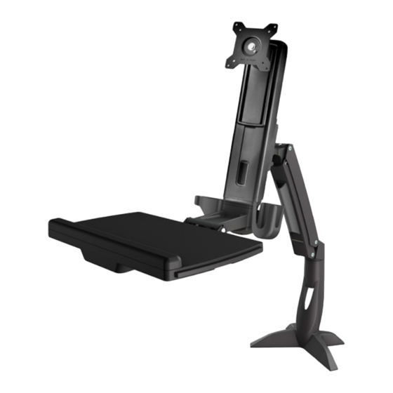
- Page 1 Sit-Stand Arm - Single Monitor *Actual product may vary from photos User Manual SKUs: ARMSTSCP1 (Black) SIT-STAND-ARM-1MS (Silver/White) For the latest information and specifications visit www.StarTech.com/ARMSTSCP1 www.StarTech.com/SIT-STAND-ARM-1MS Manual Revision: 12/20/2021...
- Page 2 This manual may make reference to trademarks, registered trademarks, and other protected names and/or symbols of third-party companies not related in any way to StarTech.com. Where they occur these references are for illustrative purposes only and do not represent an endorsement of a product or service by StarTech.com, or an endorsement of the product(s) to which this manual...
-
Page 3: Safety Statements
Säkerhetsåtgärder • Installation och/eller montering får endast göras av behöriga yrkespersoner och enligt gällande lokala förordningar för säkerhet och byggnormer. To view manuals, videos, drivers, downloads, technical drawings, and more visit www.startech.com/support... -
Page 4: Warning Statements
• Pinch hazard! Keep your fingers clear from moving components. Varningsmeddelanden • Se till att du monterar produkten i enlighet med instruktionerna. To view manuals, videos, drivers, downloads, technical drawings, and more visit www.startech.com/support... - Page 5 • Zorg dat u dit product volgens de instructies in elkaar zet. • Lees de gehele handleiding en zorg dat u de instructies begrijpt voordat u dit product in elkaar zet en gebruikt. To view manuals, videos, drivers, downloads, technical drawings, and more visit www.startech.com/support...
- Page 6 Doet u dit niet, dan kan dit leiden tot materiële schade en/ of ernstig persoonlijk letsel. • Gevaar voor beknelling! Houd uw vingers weg van de bewegende onderdelen als u. 注意 • 必ず取扱説明書に従って本製品の組み立てを行って下さい。 • 最初に取扱説明書を最後まで読み、 本製品の組み立て方をすべて理解して から組み立て作業を始めて下さい。 To view manuals, videos, drivers, downloads, technical drawings, and more visit www.startech.com/support...
- Page 7 • Non consentire ai bambini di arrampicarsi sul prodotto o di utilizzarlo senza un’adeguata supervisione. • Il prodotto è destinato all’uso in ambienti interni. Se ne sconsiglia l’impiego in ambienti esterni. To view manuals, videos, drivers, downloads, technical drawings, and more visit www.startech.com/support...
- Page 8 • Capacité de poids pour le le support de clavier quand vous utilisez l’assemblage de pince de bureau: 1.5 kg. • N’autorisez pas les enfants à grimper sur ce produit ni à l’utiliser sans surveillance. To view manuals, videos, drivers, downloads, technical drawings, and more visit www.startech.com/support...
- Page 9 • Não deixar as crianças trepar neste produto ou utilizar este produto sem a devida supervisão. • Este produto destina-se apenas a uma utilização no interior e não deve ser utilizado no exterior. To view manuals, videos, drivers, downloads, technical drawings, and more visit www.startech.com/support viii...
- Page 10 • No permita que los niños se suban a este producto o que lo utilicen sin la debida supervisión de un adulto. • El uso de este producto es solo para interiores y no debe utilizarse en exteriores. To view manuals, videos, drivers, downloads, technical drawings, and more visit www.startech.com/support...
- Page 11 2.5 kg. • Gewichtskapazität des Monitorarm wenn die Tischklemme verwendet wird: 2 nach 8 kg. • Gewichtskapazität der Tastaturhalterung wenn die Tischklemme verwendet wird: 1.5 kg. To view manuals, videos, drivers, downloads, technical drawings, and more visit www.startech.com/support...
- Page 12 Anheben oder Absenken des Displays sicher zu steuern. Andernfalls kann es zu Sachschäden und/oder schweren Personenschäden kommen. • Einklemmgefahr! Halten Sie Ihre Finger fern von beweglichen Teilen. To view manuals, videos, drivers, downloads, technical drawings, and more visit www.startech.com/support...
-
Page 13: Table Of Contents
Attach the VESA Monitor Mount to a Monitor ................25 Attach the Monitor to the Column ..................... 27 Attach the Adhesive Strip to the Keyboard ..................29 Route the Cables ............................30 To view manuals, videos, drivers, downloads, technical drawings, and more visit www.startech.com/support... - Page 14 Counterbalance the Weight of the Workstation ................35 Adjust the Monitor Swivel Tension ..................... 36 Extend the Keyboard Tray ........................37 Clean the Keyboard Tray Components ....................38 Warranty Information ................39 Limitation of Liability ................39 To view manuals, videos, drivers, downloads, technical drawings, and more visit www.startech.com/support...
-
Page 15: Product Diagram
Product Diagram Keyboard Tray Monitor Arm VESA Monitor Mount Base Column To view manuals, videos, drivers, downloads, technical drawings, and more visit www.startech.com/support... -
Page 16: Product Dimensions
Product Dimensions Front View 100 mm (3.9 in.) 75 mm (2.9 in.) 4.5 mm (0.2 in.) Top View 773.2 mm (30.4 in.) 285 mm (11.2 in.) - Page 17 Side Views 530 mm (20.9 in.) 351 mm (13.8 in.) 489 mm (19.2 in.) To view manuals, videos, drivers, downloads, technical drawings, and more visit www.startech.com/support...
- Page 18 32.5 mm (1.3 in.) 8 mm to 65 mm (0.3 in. to 2.6 in.) 124 mm (4.9 in.) 88 mm (3.5 in.) 98 mm (3.9 in.) 105.5 mm (4.1 in.) To view manuals, videos, drivers, downloads, technical drawings, and more visit www.startech.com/support...
-
Page 19: Product Information
4.4 and 17.6 lb. (2 to 8 kg) • Tools Phillips Head Screwdriver x 1 • Ratchet • ¹/₄ inch Socket • To view manuals, videos, drivers, downloads, technical drawings, and more visit www.startech.com/support To view manuals, videos, drivers, downloads, technical drawings, and more visit www.startech.com/support... -
Page 20: Package Contents
Package Contents VESA Monitor Monitor Arm Column Keyboard Tray Mount Qty: 1 Qty: 1 Qty: 1 Qty: 1 Socket Driver 6 mm Hex Key Base Adhesive Strips Qty: 1 Qty: 1 Qty: 2 Qty: 1 Plastic Washer Metal Washer M8 x 20 mm M6 x 10 mm Screws Screws... - Page 21 Basic Screw M6 x 25 mm 5 mm Hex Key M6 x 12 mm Screws Screws Qty: 4 Qty: 1 Qty: 2 Qty: 4 Clamp Screws Base Pad M4 x 10 mm 2.5 mm Hex Key Screws Qty: 4 Qty: 1 Qty: 1 Qty: 4 Grommet Plate...
- Page 22 Clamp L Bracket Clamp Screw M6 x 8 mm Screw User Manual Assembly Qty: 1 Qty: 1 Qty: 1 Qty: 1 To view manuals, videos, drivers, downloads, technical drawings, and more visit www.startech.com/support...
-
Page 23: Installation Option #1 - Grommet Mount
Attach the grommet assembly Base Base Plate Base Screws Screwdriver Figure 1 Align the Base Plate with the Assembly Holes, located on the underside of the Base. (Figure 1) To view manuals, videos, drivers, downloads, technical drawings, and more visit www.startech.com/support... - Page 24 Figure 2 Remove the Adhesive Backing from the Base Pad and affix the Base Pad to the underside of the Base to complete the Base Assembly. (Figure 2) To view manuals, videos, drivers, downloads, technical drawings, and more visit www.startech.com/support...
- Page 25 Thread the M8 x 65 mm Screw up through the underside of the Grommet Plate to complete the Screw Assembly. Position the Base over a Grommet Hole in a Desk or Table. To view manuals, videos, drivers, downloads, technical drawings, and more visit www.startech.com/support...
-
Page 26: Installation Option #2 - Desk Mount
Place Screw Assembly against the Grommet Hole on the underside of the Desk or Table. Tighten the Screw Assembly, until the Grommet Plate is connected to the base and seated tightly against the Desk or Table, using the 6 mm Hex Key. (Figure 3) Installation Option #2 - Desk Mount Attach the Desk Clamp to a Desk or Table -- or --... - Page 27 Insert the Base Screws (x 4) through the Clamp L Bracket and into the Base and tighten, using a Phillips Head Screwdriver. Base Base Pad Clamp L Bracket Figure 5 To view manuals, videos, drivers, downloads, technical drawings, and more visit www.startech.com/support...
- Page 28 (For a Desk or Table against a wall) Slide the Base Assembly between the Desk or Table and the Wall. The Base Assembly should be flush up against the edge of the Desk or Table. (Figure 6) To view manuals, videos, drivers, downloads, technical drawings, and more visit www.startech.com/support...
- Page 29 Figure 7 Align the Mounting Holes (x 4), located in the Clamp Screw Assembly, with the Lower Holes (x 4), located in the Clamp L Bracket. (Figure 7) To view manuals, videos, drivers, downloads, technical drawings, and more visit www.startech.com/support...
- Page 30 Insert the Clamp Screws (x 4) through the Clamp Screw Assembly and into the four Lower Screw Holes, located in the Clamp L Bracket and tighten, using the 5 mm Hex Key. (Figure 8) To view manuals, videos, drivers, downloads, technical drawings, and more visit www.startech.com/support...
- Page 31 Tighten the Hex Screws, located in the Clamp Screw Assembly until the Plates are seated tightly against the Desk or Table, using the 6 mm Hex Key. (Figure 9) To view manuals, videos, drivers, downloads, technical drawings, and more visit www.startech.com/support...
-
Page 32: Attach The Monitor Arm To The Base
Plastic Washer Projection Base Figure 10 Attach the Monitor Arm onto the Projection, located on the Base. Place the Plastic Washer into the Joint of the Monitor Arm. To view manuals, videos, drivers, downloads, technical drawings, and more visit www.startech.com/support... -
Page 33: Attach The Column To The Keyboard Tray
Joint, located in the Monitor Arm, and tighten, using the 6 mm Hex Key. (Figure 10) Attach the Column to the Keyboard Tray Column Holder Holder Keyboard Tray Figure 11 To view manuals, videos, drivers, downloads, technical drawings, and more visit www.startech.com/support... - Page 34 Insert the M6 x 12 mm Screws through the Assembly Holes, located in the Keyboard Tray, and into the Column and tighten, using the 5 mm Hex Key. (Figure 12) To view manuals, videos, drivers, downloads, technical drawings, and more visit www.startech.com/support...
- Page 35 Insert the M6 x 25 mm Screws (x 2) through Assembly Holes, located in the Keyboard Tray Cap, and into the Keyboard Tray and tighten, using the 5 mm Hex Key to complete the Column Assembly. (Figure 13) To view manuals, videos, drivers, downloads, technical drawings, and more visit www.startech.com/support...
-
Page 36: Attach The Column To The Monitor Arm
(Figure 14) Note: Do not fully tighten the M6 x 10 mm Screw and ensure 4 to 5 mm of space is left between the Plate and the Screw. To view manuals, videos, drivers, downloads, technical drawings, and more visit www.startech.com/support... - Page 37 Hook the M6 x 10 mm Screw, attached to the column, into the Key-Shaped Hole, located at the top of the Plate on the Monitor Arm. (Figure 15) To view manuals, videos, drivers, downloads, technical drawings, and more visit www.startech.com/support...
- Page 38 Insert the second M6 x 10 mm Screw into the hole, located on the Plate on the Monitor Arm and tighten, using the 5 mm Hex Key. (Figure 16) To view manuals, videos, drivers, downloads, technical drawings, and more visit www.startech.com/support...
-
Page 39: Attach The Vesa Monitor Mount To A Monitor
Figure 17 To enable 360 degree rotation of the Monitor, remove the Screw, located in the face of the VESA Monitor Mount, using a Phillips Head Screwdriver. (Figure 17) To view manuals, videos, drivers, downloads, technical drawings, and more visit www.startech.com/support... - Page 40 Monitor Mount and into the Monitor and tighten, using a Phillips Head Screwdriver. (Figure 18) Warning! Do not over-tighten the Screws. If you encounter resistance while tightening the Screws, stop tightening. To view manuals, videos, drivers, downloads, technical drawings, and more visit www.startech.com/support...
-
Page 41: Attach The Monitor To The Column
Hook the back of the VESA Monitor Mount onto the Plate, located on the Column. (Figure 19) To view manuals, videos, drivers, downloads, technical drawings, and more visit www.startech.com/support... - Page 42 Insert the M6 x 8 mm Screw through the Projection, located on back of the VESA Monitor Mount and into the Plate, located on the Column and tighten, using the 5 mm Hex Key. (Figure 20) To view manuals, videos, drivers, downloads, technical drawings, and more visit www.startech.com/support...
-
Page 43: Attach The Adhesive Strip To The Keyboard
Remove the Plastic Backing from the second piece of the Adhesive Strip and stick it to the surface of the Keyboard Tray so that it is aligned with the strip on the Keyboard. (Figure 21) To view manuals, videos, drivers, downloads, technical drawings, and more visit www.startech.com/support... -
Page 44: Route The Cables
Monitor Arm. Caution! Be careful not to snap the Tabs off the Cable Cover during removal. Route the Cables along the inside of the Cable Cover. (Figure 22) To view manuals, videos, drivers, downloads, technical drawings, and more visit www.startech.com/support... -
Page 45: Operation
Squeeze the Tabs, located at the top of the Cable Cover, and gently slide down, drop, and push the Cable Cover into the Monitor Arm. Operation Remove the Monitor Stored Energy Hazard! This product contains a spring mechanism which can cause the assembly and/or mounted equipment to move forcibly, and quickly, upwards. -
Page 46: Adjust The Tilt Angle Of The Monitor
Hex Key Figure 24 Adjust the Screw, located in the top of the VESA Monitor • Mount, to increase or decrease the tilt angle of the Monitor. (Figure 24) To view manuals, videos, drivers, downloads, technical drawings, and more visit www.startech.com/support... -
Page 47: Adust The Tilt Angle Of Keyboard Tray
Adust the Angle of Keyboard Tray Keyboard Tray Figure 25 Pull up or push down on the Keyboard Tray to adjust the • angle between 0° to 90°. (Figure 25) To view manuals, videos, drivers, downloads, technical drawings, and more visit www.startech.com/support... -
Page 48: Counterbalance The Weight Of The Monitor
5 mm Hex Key to turn the Screw, located in the top of the Column, to adjust the tension of the One-Touch Height Adjustment Spring. (Figure 26) To view manuals, videos, drivers, downloads, technical drawings, and more visit www.startech.com/support... -
Page 49: Counterbalance The Weight Of The Workstation
Ratchet with a 1/4 inch Socket to turn the Screw, located in the hinge of the Monitor Arm, to adjust the tension of the One-Touch Height Adjustment Spring. (Figure 27) To view manuals, videos, drivers, downloads, technical drawings, and more visit www.startech.com/support... -
Page 50: Adjust The Monitor Swivel Tension
Adjust the Adjustment Screw, located on the swivel point of • the Monitor Arm, to increase or decrease the swivel effort, using the 6 mm Hex Key. (Figure 28) To view manuals, videos, drivers, downloads, technical drawings, and more visit www.startech.com/support... -
Page 51: Extend The Keyboard Tray
Extend the Keyboard Tray Keyboard Tray Extension Extension Figure 29 Pull to extend the Extensions to the left and/or right of the • Keyboard Tray. (Figure 29) To view manuals, videos, drivers, downloads, technical drawings, and more visit www.startech.com/support... -
Page 52: Clean The Keyboard Tray Components
Keyboard Tray, and pull the corresponding Extension out from the Keyboard Tray. (Figure 31) Clean the Plastic Wrist Rest and Extensions in Warm Water mixed with a Non-abrasive Plastic-safe Cleaner. To view manuals, videos, drivers, downloads, technical drawings, and more visit www.startech.com/support... -
Page 53: Warranty Information
Limitation of Liability In no event shall the liability of StarTech.com Ltd. and StarTech.com USA LLP (or their officers, directors, employees or agents) for any damages (whether direct or indirect, special, punitive, incidental, consequential, or otherwise), loss of profits, loss of business, or any pecuniary loss, arising out of or related to the use of the product exceed the actual price paid for the product. - Page 54 Hard-to-find made easy. At StarTech.com, that isn’t a slogan. It’s a promise. StarTech.com is your one-stop source for every connectivity part you need. From the latest technology to legacy products — and all the parts that bridge the old and new — we can help you find the parts that connect your solutions.
Need help?
Do you have a question about the ARMSTSCP1 and is the answer not in the manual?
Questions and answers