
Related Manuals for SICK ISD400 Pro


Summary of Contents for SICK ISD400 Pro
- Page 1 O P E R A T I N G I N S T R U C T I O N S ISD400 Pro OPTICAL DATA TRANSMISSION SYSTEM...
- Page 2 Germany Copyright This work is protected by copyright. Any rights derived from the copyright shall be reserved for SICK AG. Repro- duction of this document or parts of this document is only permissible within the limits of the legal determination of Copyright Law.
-
Page 3: Table Of Contents
Transport inspection ............... 19 Storage ..................20 Mounting ..................21 Mounting procedure ............... 21 Mounting instructions ............21 Arranging multiple optical devices ........22 Mounting the ISD400 Pro ............24 8016441/1A78/2021-03 • © SICK AG • Subject to change without notice... - Page 4 Dimensions ................44 11.2 Performance data ..............45 11.3 Power supply ................45 11.4 Interfaces ................45 11.5 Ambient conditions ..............46 11.6 Structural design ..............46 Accessories ..................47 © SICK AG • Subject to change without notice • 8016441/1A78/2021-03...
- Page 5 Table of contents Menu structure................. 48 Index ......................51 8016441/1A78/2021-03 • © SICK AG • Subject to change without notice...
- Page 6 © SICK AG • Subject to change without notice • 8016441/1A78/2021-03...
-
Page 7: General Information
Information regarding the operating instructions These operating instructions supplement the Quick start guide and contain additional information and detailed descriptions for using the ISD400 Pro optical data transmission system from SICK AG. These operating instruc- tions are intended for skilled persons and electricians. -
Page 8: Limitation Of Liability
A list of representatives can be found on the back page. NOTE Before calling, make a note of all type label data such as type code, serial number, etc. to ensure faster proces- sing. © SICK AG • Subject to change without notice • 8016441/1A78/2021-03... -
Page 9: Ec Declaration Of Conformity
General information EC declaration of conformity → You can download the EC declaration of conformity online from "www.sick.com/isd400_pro". 8016441/1A78/2021-03 • © SICK AG • Subject to change without notice... -
Page 10: Safety
F1 (ISD400-7xx1), has a red sender and another device, F2 (ISD400-7xx2), has an infrared sender. SICK AG assumes no liability for losses or damage arising from the use of the product, either directly or indirectly. This applies in particular to use of the product that does not conform to its intended purpose and is neither described nor mentioned in this documentation. -
Page 11: Requirements For Skilled Persons And Operating Personnel
Please observe the safety notes and the warnings listed here and in other chapters of these operating instructions to reduce the possibility of risks to health and avoid dangerous situations. 8016441/1A78/2021-03 • © SICK AG • Subject to change without notice... -
Page 12: Warning Symbol On The Device
Safety Warning symbol on the device A class 1M laser is installed in the ISD400 Pro data transmission system. The device is labeled with a warning. CAUTION CAUTION LASER LASER Fig. 1: Warning symbol on the device LASER RADIATION Do not view directly with optical instruments. -
Page 13: Hazard Warnings And Operational Safety
• At distances > 6 m, the limit values for laser class 1 are not exceeded even when using monoculars with an aperture angle of any size for viewing purposes. 8016441/1A78/2021-03 • © SICK AG • Subject to change without notice... -
Page 14: Cybersecurity
Such a concept consists of organizational, technical, process- related, electronic and physical defense levels and sets up appropriate measures for the different types of risk. SICK’s products and solutions must be regarded as an integral part of this concept. -
Page 15: Product Description
1065102 0,2 ..150 m ISD400-7222 1065103 0,2 ..200 m ISD400-7321 1071580 0,2 ..200 m ISD400-7322 1071581 Table 2: ISD400 Pro optical data transmission system type overview 8016441/1A78/2021-03 • © SICK AG • Subject to change without notice... -
Page 16: Structure And Function
4 Center of optical axis, receiver 5 Ethernet female connector, M12, 4-pin, D-coded 6 Power supply male connector, M12, 4-pin, A-coded 7 Control element 8 Optical alignment aid 9 Alignment sight © SICK AG • Subject to change without notice • 8016441/1A78/2021-03... - Page 17 If a value or a piece of information in menu mode consists of more than six characters, the characters are automatically shown successively in the display. Symbols The ISD400 Pro has two distinct modes: operating mode and menu mode. Symbol Description The RUN symbol is displayed in operating mode: •...
-
Page 18: Function
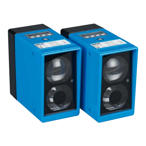
Table 5: Pushbuttons 3.2.2 Function The ISD400 Pro data transmission system consists of two optically aligned devices, one of which functions as a sender and the other as a receiver. The devices communicate over long distances and support wireless data transmission. -
Page 19: Transport And Storage
• File a complaint. NOTE Complaints regarding defects should be filed as soon as these are detected. Damage claims are only valid before the applicable complaint deadlines. 8016441/1A78/2021-03 • © SICK AG • Subject to change without notice... -
Page 20: Storage
Transport and storage Storage Please consider the following conditions when storing the ISD400 Pro: • Do not store outdoors. • Store in a dry area that is protected from dust. • Do not expose to any aggressive substances. • Protect from sunlight. -
Page 21: Mounting
• Make sure the system is a sufficient distance from other optical measu- ring devices and data transmission systems. → See Page 22, Chap- ter 5.3. 8016441/1A78/2021-03 • © SICK AG • Subject to change without notice... -
Page 22: Arranging Multiple Optical Devices
• Measuring range: 0 … 200 m • d (measuring distance): 100 m Calculation a > 100 m x 0.0055 + 0.1 m Minimum distance result a > 0.65 m © SICK AG • Subject to change without notice • 8016441/1A78/2021-03... - Page 23 Example • Measuring range: 0 … 200 m • s (Maximum travel distance): 60 m Calculation a ≥ 60 m x 0.0083 Minimum distance result a ≥ 0.5 m 8016441/1A78/2021-03 • © SICK AG • Subject to change without notice...
-
Page 24: Mounting The Isd400 Pro
Arrangement of distance sensor Dx100-2xxBxxxx to data transmission system ISD400-7xxx 1 Dx100-2xxBxxxx distance sensor 2 Reflector 3 IISD400-7xx2, infrared 4 ISD400-7xx1, red Mounting the ISD400 Pro NOTE → For mounting accessories, go to "www.sick.com/ isd400_pro", "Accessories". © SICK AG • Subject to change without notice • 8016441/1A78/2021-03... - Page 25 Fig. 9: ISD400 Pro dimensions when mounted on alignment bracket (2046052) 1. Select the mounting site for the ISD400 Pro in accordance with require- ments. Bear in mind the minimum mounting distances. → For dimen- sions, see Page 44, Chapter 11.1. The devices can be mounted horizontally or vertically on the bracket.
- Page 26 Mounting NOTE → Two transmission lines can be connected in series (cascaded). © SICK AG • Subject to change without notice • 8016441/1A78/2021-03...
-
Page 27: Electrical Connection
Incorrect wiring may result in operational faults. For this reason: • Follow the wiring notes precisely. NOTE We recommend using pre-assembled cables for the wi- ring. → For pre-assembled cables, go to "www.sick.com/ isd400_pro", "Accessories". 8016441/1A78/2021-03 • © SICK AG • Subject to change without notice... - Page 28 Electrical connection All electrical connections of the ISD400 Pro are configured as M12 round connectors. The IP 65 protection class is only achieved using screwed plug connectors. All electric circuits connected to the ISD400 Pro must be configured as PELV or SELV circuits (PELV= protective extra-low voltage, SELV = safety extra-low voltage).
-
Page 29: Connecting The Isd400 Pro Electrically
Connecting the ISD400 Pro electrically 1. Ensure that there is no voltage. 2. Connect the ISD400 Pro according to the connection diagram. → See Page 30, Chapter 6.4. 8016441/1A78/2021-03 • © SICK AG • Subject to change without notice... -
Page 30: Connection Diagrams
Supply voltage: 0 V Black Multifunctional input Table 6: Description of supply voltage male connector Ethernet Tx– Rx– Fig. 15: ISD400 Pro connection diagram, M12 female connector, 4-pin, D-coded © SICK AG • Subject to change without notice • 8016441/1A78/2021-03... - Page 31 Marking Description Send data signal, not inverted Receive data signal, not inverted – Send data signal, inverted – Receive data signal, inverted Table 7: Description of Ethernet female connector 8016441/1A78/2021-03 • © SICK AG • Subject to change without notice...
-
Page 32: Commissioning
6. Switch the laser on again on device F1 (ISD400-7xx1): Press 7. Check the alignment using the level indicator and fine-tune if necessa- ry to adjust. © SICK AG • Subject to change without notice • 8016441/1A78/2021-03... -
Page 33: Operating The Device
• Wait for approx. 2 minutes. The display will automatically switch back to the receive level indicator if no buttons are pressed. Any settings you have made will also be saved. 8016441/1A78/2021-03 • © SICK AG • Subject to change without notice... -
Page 34: Changing The Value
Alternatively, you can wait a few minutes. The display will automatically switch back to the receive level indicator if no buttons are pressed. © SICK AG • Subject to change without notice • 8016441/1A78/2021-03... -
Page 35: Parameter Description
If there are no errors pending, no errors are displayed. → See also Page 42, Chapter 10.2, list of possible errors. Table 8: Operating mode menu 8016441/1A78/2021-03 • © SICK AG • Subject to change without notice... -
Page 36: Menu Mode
• ActLow: Input active at LOW level • ActHi: Input active at HIGH level Factory setting • ActHi LsrSw Switches the laser on/off. Options • On • Off Factory setting • On © SICK AG • Subject to change without notice • 8016441/1A78/2021-03... - Page 37 • On • Off Factory setting • On OptBrk Activates or deactivates the warning message when the optical path is broken. Options • On • Off Factory setting • On 8016441/1A78/2021-03 • © SICK AG • Subject to change without notice...
- Page 38 (ISD400-7X2X) • Defines the switch-on threshold for the heating (–10 to +40 °C). Factory setting • –10 °C Reset Resets all parameters in the menu. Table 9: "Menu" menu © SICK AG • Subject to change without notice • 8016441/1A78/2021-03...
- Page 39 The "HwVers" menu is accessed via the following menu path: Operating mode → → Menu → → HwVers Press the pushbutton to display the "HwVers" parameter. Parameter Description HwVers Displays the version number Table 12: "HwVers" menu 8016441/1A78/2021-03 • © SICK AG • Subject to change without notice...
-
Page 40: Performing A Reset
→ See Page 36, Chapter 8.5.2. 2. Press the pushbutton. 3. The confirmation prompt "Sure?" appears. 4. Press the pushbutton to reset the device to its initial state. Press pushbutton to cancel the process. © SICK AG • Subject to change without notice • 8016441/1A78/2021-03... -
Page 41: Cleaning And Maintenance
For this reason: • Never use cleaning agents containing aggressive substances. • Never use pointed objects for cleaning. Maintenance The ISD400 Pro requires the following maintenance work at regular inter- vals: Interval Maintenance work To be performed by Cleaning interval depends Clean housing. -
Page 42: 10 Troubleshooting
Page 46, Chapter 11.5. shade the device from direct sunlight. • At low ambient temperatures, use a hea- ting system for the device. • At high ambient temperatures, use a cooling housing. © SICK AG • Subject to change without notice • 8016441/1A78/2021-03... -
Page 43: Possible Error Indicators
Please observe the following when disposing of the device: • Do not dispose of the device along with household waste. • Dispose of the device according to the applicable regulations in your country. 8016441/1A78/2021-03 • © SICK AG • Subject to change without notice... -
Page 44: 11 Technical Data
4 Center of optical axis, receiver 5 Ethernet female connector, M12, 4-pin, D-coded 6 Power supply male connector, M12, 4-pin, A-coded 7 Control element 8 Optical alignment aid 9 Alignment sight © SICK AG • Subject to change without notice • 8016441/1A78/2021-03... -
Page 45: Performance Data
Multifunctional output Hi: U – 3 V, Lo: <2 V Maximum output current I 100 mA Multifunctional input Hi: >8V, Lo: <5V 1) Short-circuit and overload protected Table 19: Interfaces 8016441/1A78/2021-03 • © SICK AG • Subject to change without notice... -
Page 46: Ambient Conditions
Only indoor application is UL-certified. 11.6 Structural design → See Page 44, Chapter 11.1. Dimensions Weight 800 g Materials AlSi12 Connections M12, 4-pin male connector Table 21: Structural design © SICK AG • Subject to change without notice • 8016441/1A78/2021-03... -
Page 47: 12 Accessories
Accessories 12 Accessories NOTE For additional accessories, go to "www.sick.com/isd400_ pro", "Accessories". 8016441/1A78/2021-03 • © SICK AG • Subject to change without notice... - Page 48 –074 dB –010 °C 00200h NoWarn WrnLsr WrnLvl WrnTmp WrnOvr NoErr ErrLsr ErrLvl ErrTmp ErrHv LsrOff © SICK AG • Subject to change without notice • 8016441/1A78/2021-03...
- Page 49 ActLoW MF2Out ActHi WrnLsr WrnTmp OptBrk EthLnk WrnLvl NotRdy Heat Heat –10 Reset Sure? Count OptBrk 001000 WrnTmp 001000 EthLnk 001000 Reset Sure? SwVers V1.0 … HwVers V1.0 … 8016441/1A78/2021-03 • © SICK AG • Subject to change without notice...
- Page 50 © SICK AG • Subject to change without notice • 8016441/1A78/2021-03...
- Page 51 Type code ............... 15 General information ..........21 Type label ............... 15 Minimum distance..........22, 23 Multiple sensors ............22 Notes ................ 21 Wiring notes ..............27 Procedure ..............21 8016441/1A78/2021-03 • © SICK AG • Subject to change without notice...
- Page 52 E-Mail mail@sick-sk.sk Hungary Slovenia Phone +36 1 371 2680 Phone +386 591 78849 E-Mail ertekesites@sick.hu E-Mail office@sick.si India South Africa Phone +91-22-6119 8900 Phone +27 (0)11 472 3733 E-Mail info@sick-india.com E-Mail info@sickautomation.co.za SICK AG | Waldkirch | Germany | www.sick.com...
Need help?
Do you have a question about the ISD400 Pro and is the answer not in the manual?
Questions and answers