
Related Manuals for GEA CAJ2 Series


Summary of Contents for GEA CAJ2 Series
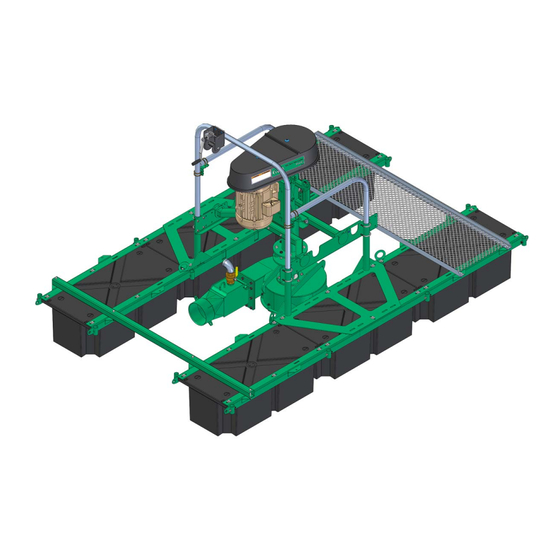
- Page 1 8” Flush Pump on Pontoon Electric Pump Operation Manual / Installation Instructions / Parts List (Original instructions) 2019-9015-009 01-2017 gea.com...
-
Page 2: Table Of Contents
......GEA Farm Technologies Canada Inc. / Division GEA Houle - General equipment warranty . - Page 3 Starting for the first time ..........Special personnel qualification required for initial commissioning .
-
Page 4: Preface
Preface About this manual Preface This is a GEA product. GEA is the manufacturer of the Houle product line. This product was formerly known under HOULE trademark. About this manual The manufacturer reserves the right to make changes due to technical developments in the data and illustrations in this manual. - Page 5 Preface About this manual Pictograms used This pictogram indicates information that will help towards better understanding of a procedure or operation. This pictogram indicates a special tool required for installation. A correction bar in the margin indicates changes to the previous edition.
-
Page 6: Manufacturer's Address
Preface Customer service Manufacturer's address GEA Farm Technologies Canada Inc. / Division GEA Houle 4591 boul. St-Joseph Drummondville, Qc, J2A 0C6 +1 819 477 - 7444 +1 819 477 - 5565 geahoule@gea.com www.gea.com Customer service Authorized Technical Dealer If necessary, please contact your nearest dealer. -
Page 7: Ec - Declaration Of Conformity For Machines In Accordance With Ec Machinery Directive 2006/42 /Ec, Annex Ii 1. A
EC - Declaration of conformity for machines in accordance with EC Machinery Directive 2006/42 /EC, Annex II 1. A Manufacturer: GEA Farm Technologies Canada Inc. / Division GEA Houle 4591 boul. St-Joseph Drummondville, Qc, J2A 0C6 We, as manufacturer, declare in sole responsibility that the machinery... - Page 8 Preface EC - Declaration of conformity for machines Authorized person for compiling and handing over Josef Schröer technical documentation: GEA Farm Technologies GmbH Siemensstraße 25-27 D-59199 Bönen ' +49 (0) 2383 / 93-70 Drummondville, 1 August 2011 Yann Desrochers (Head of Research and Development)
-
Page 9: Gea Farm Technologies Canada Inc. / Division Gea Houle - General Equipment Warranty
Preface GEA Farm Technologies Canada Inc. / Division GEA Houle - General equipment warranty GEA Farm Technologies Canada Inc. / Division GEA Houle - General equipment warranty Important notice! THIS GENERAL WARRANTY APPLIES TO ALL EQUIPMENT SOLD UNDER THE HOULE TRADEMARK. - Page 10 Preface GEA Farm Technologies Canada Inc. / Division GEA Houle - General equipment warranty 1.5.3 Extent of limited warranty This limited warranty DOES NOT cover: ● Defects caused by negligence of the Purchaser in the maintenance of the equipment, improper use resulting from failure to adhere strictly to the...
- Page 11 Preface GEA Farm Technologies Canada Inc. / Division GEA Houle - General equipment warranty 1.5.4 Warranty limitations and exclusion NO WARRANTY, ORAL OR WRITTEN, EXPRESS OR IMPLIED, OTHER THAN THE ABOVE WARRANTY IS PROVIDED IN RESPECT OF THE EQUIPMENT SOLD.
-
Page 12: Safety
If component(s)/equipment not manufactured by GEA is/are added to this GEA product, consider that new risk(s) may arise from this addition. Make sure the equipment and the environment surrounding the equipment remain safe. - Page 13 Safety Owner's obligation of care ● the installation is equipped with a floating walkway or a winch cable mechanism providing safe access to the equipment. When using a floating walkway, wearing a safety harness with a life cord attached to the walkway ramp is Mandatory for all trained personnel to access the pontoon.
-
Page 14: Explanation Of Safety Symbols
Safety Explanation of safety symbols Explanation of safety symbols The safety symbols draw attention to the importance of the adjacent text. The design of the notifications is based on ISO 3864-2 and ANSI535.6. Safety symbols and key words Danger! The signal word ”Danger” indicates an immediate threat to the lives or health of personnel. -
Page 15: Basic Safety Instructions
Safety Basic safety instructions Basic safety instructions ● Only trained personnel can operate this product to ensure safe operating methods. Make sure the personnel performing activities in connection with this product have the skills when special qualifications are required. Read the section Safety - Personnel qualifications. -
Page 16: Personnel Qualifications
Safety Personnel qualifications Personnel qualifications The manufacturer intends to determine the difference between trained personnel and qualified personnel. Trained personnel The operator was trained by the manufacturer or its legal representative to follow all safety rules, cleaning method, general maintenance as well as the operating methods. -
Page 17: Protective Devices
Safety Safety labels Protective devices This product is equipped with safety parts protecting the user against dangerous elements. Those parts must be in perfect working condition and remain in place at all times. Replace if damaged, worn and/or defective. Refer to the part number. Safety guard for drive belt (part no. - Page 18 Safety Safety labels Read the operator's manual for safety information before service and maintenance. (European model) Part no 2099-4725-130 Always turn off and lock main power before service and maintenance. (European model) Part no 2099-4725-150 Refer to section 11.1 - Appendix - Label position. 2019-9015-009 18 / 94 01-2017...
-
Page 19: Description
Description Intended Use Description Intended Use This product is exclusively designed to: ● Transfer flush liquid or water having a maximum consistency of 1/8” (3mm). Refer to section 11.3 - Appendix - Consistency test. ● Transfer liquid to flush valves or to a flush flume system. ●... -
Page 20: Product Changes
Description Functional Description Product Changes Unauthorized product modifications can have a negative impact on the safety, service life and functionality of the product. Any modifications not described in the product documentation are deemed to be prohibited. For safety reasons, do not carry out any unauthorized changes! Planned changes must be approved by the manufacturer in writing. -
Page 21: Technical Data
Technical data Pump geometric data Technical data Pump geometric data length 12' [3.66m] 16' [4.88m] Width 8' [2.44m] Height 62” [157cm] Maximum total weight 1340 lb [608kg] 1473 lb [668kg] 2019-9015-009 21 / 94 01-2017... -
Page 22: Performance Data (S.a.e.)
Technical data Performance data (S.A.E.) Performance data (S.A.E.) Maximum manure consistency 1/8” Maximum pressure 40 psi 5°C [41°F] Operating temperature Note! It is important to consider the manure consistency, the type of bedding and the quantity of bedding contained in the manure because these elements affect the performance of the pump. - Page 23 Technical data Performance data (S.A.E.) 8” Flush pump used for maximum pumping head 50 HP 40 HP 30 HP 25 HP 20 HP 15 HP Motor size Motor RPM 1760 RPM (60Hz) Pump RPM 1168 1053 Belts (4x)5VX690 (4x)BX73 (4x)BX68 (4x)BX71 (3x)BX68 (3x)BX67...
-
Page 24: Performance Data (Metric)
Technical data Performance data (Metric) Performance data (Metric) Maximum manure consistency Maximum pressure 2.76 bar 5°C [41°F] Operating temperature Note! It is important to consider the manure consistency, the type of bedding and the quantity of bedding contained in the manure because these elements affect the performance of the pump. - Page 25 Technical data Performance data (Metric) 8” Flush pump used for maximum pumping head 37 kW 30 kW 22 kW 18.5 kW 15 kW 11 kW Motor size Motor RPM 1465 RPM (50Hz) Pump RPM 1155 1037 Belts (4x)5Vx670 (3x)5vx710 (3x)5vx650 (3x)5vx650 (2x)5vx690 (2x)5vx710...
-
Page 26: Motor Specifications
Technical data Motor specifications Motor specifications GEA provides specifications and wiring diagrams related to Baldor motor(s). For any other motor brand, contact the manufacturer. Motor type Farm duty motor NEMA Standard specifications 213T, 215T, 254T, 256T, 132, 160, 180, 200, 225S... -
Page 27: Control Panel Specifications
Technical data Hydraulic hoses Control panel specifications The control panel must: ● comply with the following requirements: 2006/95/CE directives (Electrical equipment designed for use within certain voltage limits) 92/31/CEE directives (Electromagnetic compatibility) ● comply with the following harmonized standards: EN 60204-1 (Safety of machinery - Electrical equipment of machines); EN 61082-1 (Documents used in electrotechnology);... -
Page 28: Bolt Torque Chart
Technical data Lubricant specifications Bolt torque chart Bolt diameter Bolt Mat. 1/4” 5/16” 3/8” 7/16” 1/2” 9/16” 5/8” 3/4” 7/8” 1” SAE 2 16Nm 27Nm 44Nm 64Nm 94Nm 130Nm 210Nm 279Nm 420Nm (6ft-lb) (12ft-lb) (20ft-lb) (32ft-lb) (47ft-lb) (69ft-lb) (96ft-lb) (155ft-lb) (206ft-lb) (310ft-lb) SAE 5... -
Page 29: Handling And Assembly
Handling and assembly Preparation Handling and assembly Special personnel qualification required for handling Handling must be performed by a qualified forklift operator and/or qualified overhead crane or hoist operator. Installation work must be performed by trained personnel in accordance with the safety instructions. - Page 30 Handling and assembly Preparation 5.3.2 Special tools Attention! To lift the equipment, use a lifting device with a minimum capacity of: 5000 lbs (2250 kg). Description Purpose Boom Truck To lift the flush pump on pontoon. Lifting Beam To lift the flush pump on pontoon. Forklift truck To lift the equipment Lifting chains...
-
Page 31: Packing Material Disposal
● Safety fences installed around the equipment/reservoir to prevent fall. ● An electric motor meeting the technical specifications provided in this manual. Refer to section 4.4 - Technical Data - Motor specifications. ● A GEA control panel. section 4.5 - Technical Data - Control panel specifications. -
Page 32: Anchor Bolt Installation Procedure
Handling and assembly Anchor bolt installation procedure Anchor bolt installation procedure Attention! Wait at least 7 days before drilling into concrete so that the slab has harden sufficiently. Bolt diameter 3/8” [10mm] 1/2” [13mm] 3/4” [19mm] 3” [76mm] 2 3/4” [70mm] 3 3/4”... -
Page 33: Cable Clamp Assembly
Handling and assembly Cable clamp assembly Cable clamp assembly Spacing Cable Quantity of Dead End Between Diameter Clamp size clamp required Length Torque Clamps 1.125” 3.75” 7.5 ft-lb 3/16” 3/16” [29mm] [95mm] [10Nm] 1.5” 4.75” 15 ft-lb 1/4” 1/4” [38mm] [121mm] [20.3Nm] 2.25”... -
Page 34: Step 1: Unloading The Pump
Handling and assembly Step 1: Unloading the pump Step 1: Unloading the pump Warning! Do not stand under or near a lifted load, a falling load can cause death! Attention! To lift this product use a lifting device with a minimum lifting capacity of 5000 lbs [2500 kg]. -
Page 35: Step 2: Motor Support Assembly
Handling and assembly Step 2: Motor support assembly Step 2: Motor support assembly ● Assemble the motor support on the pump; ● Make sure the U-bolts (1) are placed over the stop bars (2); ● Torque to 90 ft-lb [130Nm]. 2019-9015-009 35 / 94 01-2017... -
Page 36: Step 3: Remote Grease Line Assembly
Handling and assembly Step 4: Pump pivots assembly Step 3: Remote grease line assembly ● Assemble the remote grease lines, as illustrated; ● Snug fit, do not torque. 5.10 Step 4: Pump pivots assembly ● Install the pump pivots using washers, lock washers and the nuts provided while making sure the longest portion of the pivots are placed toward the pump discharge;... -
Page 37: Step 5: Control Panel Installation
Handling and assembly Step 5: Control panel installation 5.11 Step 5: Control panel installation Warning! Risk of electric shock! Connect the control panel and all conductive equipments to an equipotential bond. This symbol indicates that the terminal must be connected to earth ground. -
Page 38: Step 6: Electric Motor Installation
Step 6: Electric motor installation 5.12 Step 6: Electric motor installation Attention! GEA provides specifications and wiring diagrams related to Baldor motor(s). For any other motor brand, contact the manufacturer. 5.12.1 Motor installation ● Loosen bolt (1); ● Pull the support;... - Page 39 Handling and assembly Step 6: Electric motor installation Single motor ● Insert the bolts (2) behind the motor support; ● Secure the motor in place using lock washers (3) and nuts (4); ● Tighten. Refer to section 4.8 - Technical data - Bolt torque chart. 2019-9015-009 39 / 94 01-2017...
- Page 40 Handling and assembly Step 6: Electric motor installation Double motor ● Insert the bolts (2) behind the motor support; ● Place the adaptor over the motor support; ● Secure using lock washers (3) and nuts (4); ● Tighten; ● Insert the bolts (5) behind the adaptor; ●...
- Page 41 Handling and assembly Step 6: Electric motor installation 5.12.2 Motor direction of rotation Warning! Risk of electric shock! Electric wiring and connection must be performed by an electrician. Caution! Risk of electric shock! To avoid incidental electric cable break, keep additional cable length between the control panel and the pontoon to ensure that the pontoon can move freely in the lagoon or pit.
- Page 42 Handling and assembly Step 6: Electric motor installation 5.12.3 Lower guard assembly Caution! Risk of injuries! Always install the sliding plate over the lower guard to restrain access to the pulleys. ● Remove the segments of the sliding plate according to the HP of the motor. Refer to the following table.
- Page 43 Handling and assembly Step 6: Electric motor installation 5.12.4 Pulleys assembly ● Make sure the external cut-off switch is shut down and locked; ● Assemble the keys, hubs (10) and pulleys (11) on the shafts. Dry mount assembly, never use lubricants or antiseize compounds on the hub and hub mounting area;...
- Page 44 Handling and assembly Step 6: Electric motor installation 5.12.5 Motor belt installation Caution! Pinch point hazard! Wear protective gloves when handling the belts and pulleys. ● Install the belt (12); ● Pull the motor support to hold the belt on the pulleys. ●...
-
Page 45: Step 6: Float Preparation
Handling and assembly Step 6: Float preparation 5.12.6 Protective guard installation ● Insert the guard support (20) into the post (21). Make sure the support does not contact the hubs (22); ● Place the upper guard (23) over the support and secure with washers and nuts. -
Page 46: Step 7: Pontoon Assembly
Handling and assembly Step 7: Pontoon assembly 5.14 Step 7: Pontoon assembly 5.14.1 12ft Pontoon Note! Do not tighten the bolts/U-bolts until the pontoon assembly is completed or unless otherwise instructed. Step A: Floats and steel angles assembly Note! Assemble the pontoon on a flat and level surface. Note! Place the anti-slip surface upward. - Page 47 Handling and assembly Step 7: Pontoon assembly Step B: Cross member and platform assembly ● Install a cross member using 4 [½” - 13NC - 3¾”] bolts, washers, lock washers and nuts, DO NOT TIGHTEN; ● Place the platform over the assembly; ●...
- Page 48 Handling and assembly Step 7: Pontoon assembly Step C: Supports assembly ● Place a pontoon support over each float assembly; ● Secure using 8 [½” - 13NC - 3”] bolts, washers, lock washers and nuts, DO NOT TIGHTEN; ● Assemble the pump supports on the support tubes using 3¼” U-bolts and lock nuts, DO NOT TIGHTEN;...
- Page 49 Handling and assembly Step 7: Pontoon assembly Step D: Handrail pipes and winch assembly ● Insert the handrail pipes into the sleeves of the tube supports; ● Install the winch on the winch support using 3 [3/8” - 16NC - 1¼”] bolts, lock washers and nuts, tighten;...
- Page 50 Handling and assembly Step 7: Pontoon assembly Step E: Pontoon shimming ● Using a proper lifting device, carefully lift the pontoon by its lifting rings; ● Place some 6” x 6” [154mmx154mm] beams under each float to shim the pontoon. Make sure the pontoon is stable. 2019-9015-009 50 / 94 01-2017...
- Page 51 Handling and assembly Step 7: Pontoon assembly Step F: Motor installation Attention! To lift this product use a lifting device with a minimum lifting capacity of 5000 lbs [2500 kg]. The lifting capacity only includes the weight of the product. ●...
- Page 52 Handling and assembly Step 7: Pontoon assembly Step G: Handrails and cable installation ● Insert a post inside each angle frame sleeve; ● Secure using 8 [½” -13NC - 2½”] bolts and nylon lock nuts, as illustrated. Tighten; ● Insert the steel cable through each post located on the same side; ●...
- Page 53 Handling and assembly Step 7: Pontoon assembly Step H: Winch cable installation Note! To prevent seizing of metal parts, apply a significant coat of grease when specified. ● Install the winch handle; ● Through the inside of the reel, run the cable in the ½”...
- Page 54 Handling and assembly Step 7: Pontoon assembly Step I: Pump hoistline installation Note! To prevent seizing of metal parts, apply a significant coat of grease when specified. ● Insert a cable protector through the ring located next to the pump ball valve;...
- Page 55 Handling and assembly Step 7: Pontoon assembly 5.14.2 16ft Pontoon Note! Do not tighten the bolts/U-bolts until the pontoon assembly is completed or unless otherwise instructed. Step A: Floats and steel angles assembly Note! Assemble the pontoon on a flat and level surface. Note! Place the anti-slip surface upward.
- Page 56 Handling and assembly Step 7: Pontoon assembly Step B: Cross member assembly ● Install 2 cross members using 8 [½” - 13NC - 3¾”] bolts, washers, lock washers and nuts, DO NOT TIGHTEN YET; 2019-9015-009 56 / 94 01-2017...
- Page 57 Handling and assembly Step 7: Pontoon assembly Step C: Pontoon supports assembly ● Place a pontoon support over each float assembly; ● Secure using 10 [½” - 13NC - 3”] bolts, washers, lock washers and nuts, DO NOT TIGHTEN YET; 2019-9015-009 57 / 94 01-2017...
- Page 58 Handling and assembly Step 7: Pontoon assembly Step D: Platforms assembly ● Place the platforms over the steel angles while making sure they clear the lifitng rings. 2019-9015-009 58 / 94 01-2017...
- Page 59 Handling and assembly Step 7: Pontoon assembly Step E: Pump support assembly ● Assemble the pump supports on the support tubes using 3¼” U-bolts and lock nuts, DO NOT TIGHTEN YET; 2019-9015-009 59 / 94 01-2017...
- Page 60 Handling and assembly Step 7: Pontoon assembly Step F: Handrail pipes and winch assembly ● Insert the handrail pipes into the sleeves of the support tubes; ● Install the winch on the winch support using 3 [3/8” - 16NC - 1¼”] bolts, lock washers and nuts, tighten;...
- Page 61 Handling and assembly Step 7: Pontoon assembly Step G: Pontoon shimming ● Using a proper lifting device, carefully lift the pontoon by the lifting rings; ● Place some 6” x 6” [154mmx154mm] beams under each float to shim to pontoon. Make sure the pontoon is stable. 2019-9015-009 61 / 94 01-2017...
- Page 62 Handling and assembly Step 7: Pontoon assembly Step H: Motor installation Attention! To lift this product use a lifting device with a minimum lifting capacity of 5000 lbs [2250 kg]. The lifting capacity only includes the weight of the product. ●...
- Page 63 Handling and assembly Step 7: Pontoon assembly Step I: Handrails and cable installation ● Insert a post inside each angle frame sleeve; ● Secure using 10 [½” -13NC - 2½”] bolts and nylon lock nuts, as illustrated. Tighten; ● Insert the steel cable through each post located on the same side; Refer to section 5.6 - Cable clamp assembly.
-
Page 64: Step 8: Winch Cable Installation
Handling and assembly Step 8: Winch cable installation 5.15 Step 8: Winch cable installation Note! To prevent seizing of metal parts, apply a significant coat of grease when specified. ● Install the winch handle; ● Through the inside of the reel, run the cable in the ½”... - Page 65 Handling and assembly Step 8: Winch cable installation Note! To prevent seizing of metal parts, apply a significant coat of grease when specified. ● Place a cable thimble inside the hoisting ring located next to the ball valve; ● Run the cable around the thimble and inside the hoisting ring;...
-
Page 66: Step 9: Motor Safety Chain Assembly
Handling and assembly Step 9: Motor safety chain assembly 5.16 Step 9: Motor safety chain assembly ● Insert the chain in the housing of the winch; ● Use a chain link to secure the chain end to one chain ring; ●... -
Page 67: Step 10: Pontoon Installation In A Pit Or A Lagoon
Handling and assembly Step 10: Pontoon installation in a pit or a lagoon 5.17 Step 10: Pontoon installation in a pit or a lagoon Warning! Shutdown is required! shut the main power supply and lock with a locking device. Post a sign on the panel stating: ”Do not turn on, maintenance work in progress”... -
Page 68: Step 11: Evacuation Line Connection
Handling and assembly Step 11: Evacuation line connection 5.18 Step 11: Evacuation line connection Caution! Risk of fatal injuries! Only trained personnel is allowed to access the pontoon. Caution! Risk of injuries! Allow only one person at a time on the pontoon. The pontoon is designed to support additional weight equivalent to one person. - Page 69 Handling and assembly Step 11: Evacuation line connection ● Wind the hoistline using the winch until the pump discharge is out of the manure and safely accessible; ● Assemble evacuation line [straight adapter, collar and the flexible hose], as illustrated; ●...
-
Page 70: Step 12: Height Adjustment Of The Pump
Handling and assembly Step 12: Height adjustment of the pump 5.19 Step 12: Height adjustment of the pump Caution! Risk of injuries! Make sure the cut-off switch is shut down and locked before accessing the pontoon. The pontoon is unstable when the pump operates. Attention! Never allow the manure to flow over the dotted line, as illustrated. - Page 71 Handling and assembly Step 12: Height adjustment of the pump Attention! If the pump is submerged too deep, remove the pontoon from the pit or lagoon to proceed with the heigth adjustment of the pump. Before removing the pontoon, estimate how high the pump should be raised. ●...
-
Page 72: Starting For The First Time
Starting for the first time Safety instructions for initial commissioning Starting for the first time Special personnel qualification required for initial commissioning Initial commissioning must be performed by trained personnel in accordance with the safety instructions. Read the section Safety - Personnel qualifications. Safety instructions for initial commissioning Warning! Do not operate this product until the initial commissioning checklist is... -
Page 73: Initial Commissioning Checklist
Starting for the first time Initial commissioning checklist Initial commissioning checklist This checklist must be completed by the dealer and the customer. The initial commissioning steps intend to test the product to validate its functionality. Therefore, the dealer and the customer must operate the product to make sure the product is assembled and/or installed according to the manufacturer's instructions. -
Page 74: Checks After Initial Commissioning
Hand over warranty registration form The warranty registration form must be completed and signed by the customer and the dealer. The warranty registration form must be returned to GEA Farm Technologies Canada Inc. / Division GEA Houle to validate the warranty. -
Page 75: Operation
Operation Operating the product Operation Special personnel qualification required for operation Operation must be performed by qualified personnel in accordance with the safety instructions. Read the section Safety - Personnel qualifications. Safety instructions for operation Read the section Safety. Operating the product 7.3.1 Pump in transfer mode Caution! -
Page 76: Operating Faults
Operating faults Troubleshooting possible faults Operating faults Special personnel qualification required for troubleshooting Troubleshooting must be performed by trained personnel in accordance with the safety instructions. Read the section Safety - Personnel qualifications. Safety instructions for troubleshooting Warning! Shutdown is required! shut the main power supply and lock with a locking device. - Page 77 Operating faults Troubleshooting possible faults Symptom Possible cause Solution Motor runs Drive system is Check belt integrity. without pumping. disadjusted. Check belt tension. Adjust, if required. Refer to section 5.12.5 - Handling and assembly - Motor belt installation. Check pulleys assembly. Refer to 5.12.4 - Handling and assembly - Pulleys assembly.
- Page 78 Operating faults Troubleshooting possible faults Symptom Possible cause Solution Pump Wrong manure Perform a consistency performance consistency. test. Refer to section 11.3 decreases. - Appendix - Consistency test. The maximum manure consistency is 1/8” [3mm].. Add water and agitate until proper consistency is reached.
-
Page 79: Maintenance
Read the section Safety. Scheduled maintenance responsibilities Note! When operating this GEA Houle product using other manufacturer's components and/or products such as a PTO, a tractor, a motor, a pump, etc., ALWAYS perform maintenance of the component and/or product as recommended by its manufacturer. - Page 80 Maintenance Scheduled maintenance responsibilities 8” flush pump on pontoon Task Maintenance to be performed by trained personnel Motor support threaded bolts lubrication Winch lubrication Ball valve lubrication Check the bolts torque Check the motor belt tension Visual inspection Upper bearing lubrication Lower bearing lubrication Maintenance to be performed by a dealer Impeller and housing inspection...
-
Page 81: Motor Support Threaded Bolts Lubrication
Maintenance Scheduled maintenance responsibilities Motor support threaded bolts lubrication Note! To prevent seizing of metal parts, apply a significant coat of grease when performing the following maintenance. ● Apply PRECISION™ general purpose EP2 grease each threaded rod of the motor support. Winch lubrication Note! To prevent seizing of metal parts, apply a significant coat of grease... -
Page 82: Ball Valve Lubrication
Maintenance Visual inspection Ball valve lubrication Note! To prevent seizing of metal parts, apply a significant coat of grease when performing the following maintenance. ● Apply PRECISION™ general purpose EP2 grease over the handle nuts. Check bolts torque ● Check the tightness of all bolts and anchor bolts; ●... -
Page 83: Upper Bearing Lubrication
Maintenance Lower bearing lubrication 9.10 Upper bearing lubrication Attention! Slowly lubricate this bearing to avoid applying significant pressure on the seals. Applying too much pressure will damage the seals inside the bearing. Note! Avoid splashing water over the bearing unit! If water contacts the bearing unit, wipe clean the bearing and grease immediately to prevent premature wear. -
Page 84: Disconnecting The Evacuation Line From The Pump
Maintenance Disconnecting the evacuation line from the pump 9.12 Disconnecting the evacuation line from the pump Warning! Shutdown is required! shut the main power supply and lock with a locking device. Post a sign on the panel stating: ”Do not turn on, maintenance work in progress”... -
Page 85: Decommissioning
Decommissioning Final decommissioning/disposal Decommissioning 10.1 Special personnel qualification required for decommissioning Decommissioning may only be performed by specially qualified personnel in accordance with the safety instructions. Read the section Safety - Personnel qualifications. 10.2 Safety instructions for decommissioning Read the section Safety. 10.3 Final decommissioning/disposal After final decommissioning, handle all components properly and dispose of... -
Page 86: Appendix
Appendix Label position Appendix 11.1 Label position US + EU 2099-4720-010 2099-4721-000 2010-4700-400 2099-4725-240 2099-4725-210 US + EU 2099-4725-110 2099-4725-100 2099-4725-150 US + EU US + EU US + EU 2099-4701-240 2099-4700-390 2099-4725-010 US = American label / EU = European label 2019-9015-009 86 / 94 01-2017... -
Page 87: Pumping Head Calculation
Appendix Pumping Head Calculation 11.2 Pumping Head Calculation Note! Read the following information before calculating and filling the Pumping Head Formula. 11.2.1 Transfer rate ● In SAE, the transfer rate is expressed in US GPM. ● In metric, the transfer rate is expressed in Liters per minute. 11.2.2 Elevation (X) The elevation is the height difference between the reception pit bottom and the top of the storage pit. - Page 88 * PVC adaptor 45 ' 12¾” to 15” PVC adaptor 304,8 mm to 14 m 381 mm * For 12” [300 mm] GEA Houle steel components, use the Friction Loss Coefficient for PVC pipes. 2019-9015-009 88 / 94 01-2017...
- Page 89 Appendix Pumping Head Calculation 11.2.6 Friction Loss Coefficient of PVC Piping Liquid and manure consistency Litres per Diametre Gallons 1/8” 1/4” 1/2” 3/4” minute Water per minute (3mm) (6mm) (12mm) (18mm) 0.0526 0.0599 0.0710 0.1041 0.1519 0.0980 0.1117 0.1323 0.1940 0.2832 3”...
- Page 90 Appendix Pumping Head Calculation 11.2.7 Friction Loss Coefficient for Flexible Hoses and Steel Piping Liquid and manure consistency Litres per Diametre Gallons 1/8” 1/4” 1/2” 3/4” minute Water per minute (3mm) (6mm) (12mm) (18mm) 0.0682 0.0777 0.0920 0.1350 0.1970 0.1271 0.1448 0.1715 0.2516...
- Page 91 Appendix Pumping Head Calculation 11.2.8 Pumping Head Formula INFORMATION FORMULA Type of Linear TOTAL Intended transfer Evacuation line Manure Friction lost piping and equivalence or rate diameter consistency coefficient material pipe/hose length 1200 USGPM 1.525' 8” [205mm] 50' [15.24m] 0.0305 Hose [0.47m] [4550 lpm]...
-
Page 92: Consistency Test
11.3 Consistency test GEA Houle determined the following method to verify if the viscosity of the liquid manure is suitable for this product. 1. Set a pail on a level surface and install a 24” [60cm] round plate at the center of the pail. -
Page 93: Abbreviations
Appendix Abbreviations 11.4 Abbreviations Terms Explanation Terms Explanation Ø diameter European Community clockwise counterclockwise facsimile I.D. inside diameter Inc. Incorporated national coarse O.D. outside diameter power take off polyvinyl chloride Society Automotive Quebec Engineers United States of America World Wide Web Units Explanation Units... - Page 94 Excellence • Passion • Integrity • Responsibility • GEA-versity GEA Group is a global engineering company with multi-billion euro sales and operations in more than 50 countries. Founded in 1881, the company is one of the largest providers of innovative equipment and process technology.
Need help?
Do you have a question about the CAJ2 Series and is the answer not in the manual?
Questions and answers