Table of Contents
Advertisement
ATTACH YOUR RECEIPT HERE
Serial Number _____________________________ Purchase Date ______________________
Questions, problems, missing parts? Before returning to your retailer, call our
customer service department at 1-888-922-2336, 7:00 a.m. – 12:00 a.m., CST(daily) or
e-mail us at customerservice@academy.com, or live chat at www.academy.com.
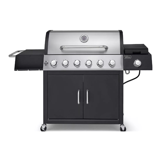
6-BURNER
LP GAS GRILL
Model #6 Burner SNR_177313
Advertisement
Table of Contents

Related Manuals for Outdoor Gourmet 177313


Summary of Contents for Outdoor Gourmet 177313
- Page 1 6-BURNER LP GAS GRILL Model #6 Burner SNR_177313 ATTACH YOUR RECEIPT HERE Serial Number _____________________________ Purchase Date ______________________ Questions, problems, missing parts? Before returning to your retailer, call our customer service department at 1-888-922-2336, 7:00 a.m. – 12:00 a.m., CST(daily) or e-mail us at customerservice@academy.com, or live chat at www.academy.com.
-
Page 2: Table Of Contents
TABLE OF CONTENTS Safety Information ........................Package Contents ........................Hardware Contents ........................Preparation ..........................Assembly Instructions ......................8-21 Operation Instructions ......................22-26 Care and Maintenance ......................27-30 Troubleshooting ........................Recipes ............................ Warranty ............................33 Replacement Parts List ......................34-35 Assembler/Installer: This manual contains important information necessary for the proper assembly and safe use of this appliance. -
Page 3: Safety Information
SAFETY INFORMATION Please read and understand this entire manual before attempting to assemble, operate or install the product. If you have any questions regarding the product, please call customer service at: 1-888-922-2336, 7:00 a.m. - 12:00 a.m., CST(daily) or e-mail us at customerservice@academy. com, or live chat at www.academy.com. - Page 4 SAFETY INFORMATION WARNING • Do not place the grill under overhead combustible construction or awnings. Minimum clearance from sides and back of unit to combustible construction, 36 inches (914.4mm) from sides and back. NOTE: The installation must conform with local codes or, in the absence of local codes, with either the National Fuel Gas Code, ANSI Z223.1/NFPA 54, Natural Gas and Propane Installation Code, CSA...
-
Page 5: Package Contents
PACKAGE CONTENTS... - Page 6 PACKAGE CONTENTS...
-
Page 7: Hardware Contents
HARDWARE CONTENTS M5x10 M6x16 M4x10 Tool Door Washer Bolt Bolt Spring Bolt Upper Washer Hinge Qty. 2 Qty. 20 Qty. 35 Qty. 6 Qty. 3 Qty. 2 Qty. 2 M10-M6 Wrench Washer handle bezel Qty. 1 Qty. 2 Qty. 2 PREPARATION Before beginning assembly of product, make sure all parts are present. -
Page 8: Assembly Instructions
ASSEMBLY INSTRUCTIONS Attach the cart bottom shelf front facing (37) to the cart bottom shelf (28) with 3 M6x16 bolts (A). Hardware Used M6x16 Bolt Attach the right cart panel assembly (27) to the cart bottom shelf front facing and the cart bottom shelf with 3 M6x16 bolts (A). - Page 9 ASSEMBLY INSTRUCTIONS Attach the cart rear panel (26) to the right cart side panel assembly with 2 M6x16 bolts. Hardware Used M6x16 Bolt Attach the left cart panel assembly (24) to the cart bottom shelf front facing, the cart bottom shelf and the cart rear panel with 5 M6x16 bolts (A).
- Page 10 ASSEMBLY INSTRUCTIONS Attach the two locking swivel casters (31) and the two non-locking swivel casters (32) to the cart assembly with the M10-M6 wrench (I). Hardware Used M10-M6 Wrench Attach the upper front door brace (30) to the left cart side panel assembly and the right cart side panel assembly with 4 M6x16 bolts (A).
- Page 11 ASSEMBLY INSTRUCTIONS Attach the magnet (29) to the cart bottom shelf with 2 M4x10 bolts (F). Hardware Used M4x10 Bolt Insert the door lower axis in the left door assembly (33) into the hole on the cart bottom shelf front facing, and insert the door upper hinge (G) into the hole on the upper front door brace and the upper hole on the left door assembly (33) as shown.
- Page 12 ASSEMBLY INSTRUCTIONS Attach the door handle (34) to the left door assembly and the right door assembly, with 4 M5x12 bolts (D). Hardware Used M5x10 Bolt Attach the cart rack (25) to the left cart panel and cart bottom shelf with 4 M5X12 Bolts (D). Hardware Used M5x10 Bolt...
- Page 13 ASSEMBLY INSTRUCTIONS Attach the accessory rack (36) to the two holes inside the right door as shown. Assemble the grill body assembly (5) onto the cart assembly with 4 M6x16 bolts (A). Hardware Used M6x16 Bolt...
- Page 14 ASSEMBLY INSTRUCTIONS Attach the lid handle (4) and lid handle bezel (H) to the lid with 2 M6x16 bolts (A),2 M6 spring washers (E) and 2 M6 washers (C). Hardware Used M6x16 Bolt M6 Washers M6 spring washers Lid handle bezel Remove pre-assembled wingnut from the temp gauge (1), then attach the temp gauge (1) and temp gauge bezel (2) to the lid.
- Page 15 ASSEMBLY INSTRUCTIONS Attach the bottle opener (10) to the control panel, with 2 M6x16 bolts (A). Hardware Used M6x16 Bolt Attach 3 tool peg (B) to the Left Side Condiment Tray (16). Hardware Used Tool peg...
- Page 16 ASSEMBLY INSTRUCTIONS Attach the left side condiment Tray to the left side table assembly (15) with 4 pcs M5x12 bolts (D). Hardware Used M5x10 Bolt Attach the side table handle (14) to left side table assembly with 2 M6x16 bolts (A). Hardware Used M6x16 Bolt...
- Page 17 ASSEMBLY INSTRUCTIONS Pre-Assemble 2 M6x16 bolts (A) onto the grill body assembly and do not tighten them. Make sure to leave a 5mm gap between the bolt and grill body’s end cap. Then hang the left side table assembly on the bolts and fasten the left side table assembly with 2 M6x16 bolts (A) and 2 M5x12 bolts (D) and tighten all bolts.
- Page 18 ASSEMBLY INSTRUCTIONS Attach the side burner control panel assembly (22) to the right side burner body assembly (21) with 4 M5x10mm bolts (D). Hardware Used M5x10 Bolt Pre-Assemble 2 M6x16 bolts (A) onto the grill body assembly and do not tighten them. Make sure to leave a 5mm gap between the bolt and grill body’s end cap.Then hang the right side burner body assembly on the bolts and fasten the right side burner body assembly with 2 M6x16 bolts (A) and 2 M5x12 bolts (D) and tighten all bolts.
- Page 19 ASSEMBLY INSTRUCTIONS Use 2 M4x10 bolts (F) to assemble the side burner valve assembly (5j) and control knob bezel (23) to the side burner control panel assembly. Hardware Used M4x10 Bolt Use 2 M4x10 bolts (F) and 2 M4 washer (J) to assemble side burner (20) onto the right side burner body assembly, (please ensure that the gas valve orifice is correctly positioned...
- Page 20 ASSEMBLY INSTRUCTIONS Assemble the ignition wire to the side burner electrode. Assemble the 7 control knobs (11) to the valve stems of main burner and side burner valve. Apply light pressure to secure the knob firmly. Make sure that the flat end of the stem is aligned with the D-shape hole in control knob (with the triangle pointing upwards).
- Page 21 ASSEMBLY INSTRUCTIONS Put the grease pan (12) into the bottom of grill body assembly and put grease cup (13) into the holding bracket of grease pan (12). Put six heat tents (9) in place over each burner. Put side burner rack (19) onto the right side burner body assembly.
-
Page 22: Operation Instructions
OPERATION INSTRUCTIONS CHECKING FOR LEAKS After all connections are made, check all connections and fittings on the LP gas tank valve, gas hose and regulator for leaks with a water and soap solution. To prevent fire or explosion while testing for a leak: •... - Page 23 OPERATION INSTRUCTIONS CONNECTING GAS CYLINDER The propane gas supply cylinder to be used must be constructed and marked in accordance with the Specifications for LP Gas Cylinders of the U.S. Department of Transportation (D.O.T.) or the National Standard of Canada, CAN/CSA-B339, Cylinders, Spheres and Tubes for Transportation of Dangerous Goods;...
- Page 24 OPERATION INSTRUCTIONS NOTE: Other cylinders may be acceptable for use with this appliance provided they are compatible with the appliance nesting hole and retention means. Refer to Step 23 of the Assembly Instructions for correct cylinder to cylinder holder connection. WARNING ALL INSTRUCTIONS AND SAFEGUARDS ON THIS PAGE MUST BE FOLLOWED TO PREVENT FIRE, DAMAGE AND/OR INJURY.
- Page 25 OPERATION INSTRUCTIONS Lighting The Grill Before first use: Remove all hangings or plastic straps, if present. Before you cook on your new gas grill, it is important to clean your grill with heat. To do this, operate the grill for approximately 15 minutes with the lid closed and the control knob in the highest position.
- Page 26 OPERATION INSTRUCTIONS LIGHTING THE GRILL WITH A MATCH 1. Open the lid. 2. Insert a match in the end of the match holder that is installed on the right door assembly. 3. Light the match. 4. Immediately place the lit match through the spaces in the grill gates near the ports of the burner between the heat tents as shown.
-
Page 27: Care And Maintenance
CARE AND MAINTENANCE Proper and regular care is essential to maintain the appearance and performance of this product, just like any other appliance. Timely maintenance will ensure its longevity and optimal functionality. Cooking Grates The best time to ‘burn-off’ the cooking grates is after every use (approx. 15 minutes). The grill is already hot from cooking thus requiring less fuel to obtain necessary temperature for ‘burn-off’. - Page 28 CARE AND MAINTENANCE Burner Assembly Removing The Burner Assembly 1. Make sure all control knobs are in the OFF position, gas supply valve is closed, and the gas hose is disconnected from the gas supply. 2. Open lid and remove warming rack, cooking grates, heat tents, clip for burner, ignition chain and main burner.
- Page 29 CARE AND MAINTENANCE Cleaning the Burner Assembly – Make sure the grill is cool 1. Turn gas off at the control knobs and LP gas cylinder. 2. Disconnect LP gas cylinder from regulator and hose. 3. Remove warming rack, cooking grates and heat tents. 4.
- Page 30 CARE AND MAINTENANCE WARNING DO NOT mix old and new batteries. DO NOT mix alkaline, standard (Carbon-Zinc), or rechargeable (Nickel-Cadmium) batteries. DO NOT dispose of batteries in fire. Improper disposal may cause batteries to leak or explode. TROUBLESHOOTING If you have any questions regarding the product, please call customer service at 1-877-447-4768, 8:00 a.m.
-
Page 31: Troubleshooting
TROUBLESHOOTING PROBLEM POSSIBLE CAUSE CORRECTIVE ACTION The burner will not 1. Match not reaching burners 1. Use match holder found in light with a match. (when holding match with cabinet door. hand). 2. Check fuel level and refill tank if 2. -
Page 32: Recipes
RECIPES Perfectly Grilled Steak Level: Easy Total: 30 min Prep: 15 min Cook: 15 min Yield: 4 servings Ingredients Four 1 1/4-to-1 1/2-inch-thick boneless rib-eye or New York strip steaks (about 12 ounces each) or filets mignons (8 to 10 ounces each), trimmed 2 tablespoons extra-virgin olive oil Kosher salt and freshly ground pepper Directions... -
Page 33: Warranty
Warranty Information Manufacturer warrants this Product to be free from defects in workmanship and materials for a period of 1 year from the date of purchase, PROVIDED claims are submitted, in writing, with proof of purchase. If any part of this item fails because of a manufacturing defect within the Limited Warranty Period, Manufacturer offers to replace such part(s) provided that such parts have not been improperly repaired, altered, or tampered with or subject to misuse, abuse or exposed to corrosive conditions. -
Page 34: Replacement Parts List
REPLACEMENT PARTS LIST... - Page 35 REPLACEMENT PARTS LIST For replacement parts, call our customer service department at 1-888-922-2336, 7:00 a.m. – 12:00 a.m.,CST(daily) or e-mail us at customerservice@academy.com, or live chat at www.academy.com.
Need help?
Do you have a question about the 177313 and is the answer not in the manual?
Questions and answers