Table of Contents

Related Manuals for Outdoor Gourmet GR2215101-OG-00


Summary of Contents for Outdoor Gourmet GR2215101-OG-00
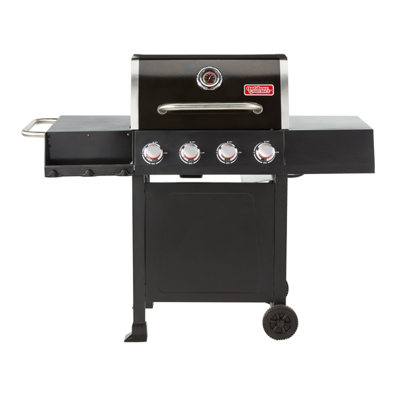
- Page 1 User Manual 4 BURNER GAS GRILL Model number: GR2215101-OG-00 Ref. style: FSOGBG1106 Please keep this instruction manual for future reference Customer Service: (888) 837-1380, 8:00am to 5:00pm, Monday thru Friday, Pacific Standard Time (Made in China)
-
Page 2: Table Of Contents
Table of Contents Warnings --------------------------------------------------------------------------------------------- P.2–7 To o l s R e q u i r e d - - - - - - - - - - - - - - - - - - - - - - - - - - - - - - - - - - - - - - - - - - - - - - - - - - - - - - - - - - - - - - - - - P.7 Product Diagram---------------------------------------------------------------------- P.8 Parts List ------------------------------------------------------------------------------------- P.9–10 Hardware List --------------------------------------------------------------------------------------- P.11... -
Page 3: Warnings
WARNINGS SAFETY LABELS DANGER: Indicates an imminent hazardous situation which if not avoided will result in death or serious injury. WARNING: Be alert to the possibility of serious bodily injury if the instructions are not followed. Be sure to read and carefully follow all of the messages. CAUTION: Indicates a potentially hazardous situation, which, if not avoided, may result in minor or moderate injury. - Page 4 DANGER (a) Do not store a spare LP-gas cylinder under or near this appliance; (b) Never fill the cylinder beyond 80 percent full; (c) If the information in (a) and (b) is not followed exactly, a fire causing death or serious injury may occur.
- Page 5 Grill is hot when in use. To avoid burns: DO NOT attempt to move the grill. Lock the wheels so the unit does not accidentally move. Wear protective gloves or oven mitts. DO NOT touch any hot grill surfaces. ...
- Page 6 The cylinder should ALWAYS be put in an upright position. DANGER DO NOT connect this grill to an existing #510 POL cylinder valve with Left hand threads. The Type 1 valve can be identified with the large external threads on the valve outlet. ...
- Page 7 INSTALLING GAS CYLINDER 1. Check that cylinder valve is closed by turning knob clockwise. 2. Pull the tank fixing bar up and tighten. 3. Place cylinder into tank holder and fix it in place with the tank fixing bar. Place cylinder such that valve opening faces the right side table and so that hose is not kinked/damaged.
-
Page 8: Tools Required
TO DISCONNECT LP CYLINDER: Turn the burner valves off. Turn the tank valve off fully (turn clockwise to stop). Detach the regulator assembly from the tank valve by turning the quick coupling nut counterclockwise. CAUTION When installing LP cylinders the pressure regulator and hose supplied by the manufacturer MUST be used with the appropriate cylinder. -
Page 9: Product Diagram
PRODUCT DIAGRAM Page 8 of 29 20151106-Ver1... -
Page 10: Parts List
PARTS LIST 1. Warming Rack 2. Cooking Grate 3. Flame Tamer Qty: 1pc Qty: 2pcs Qty: 4pcs 4. Grill Body assembly 5. Hook 6. Towel Bar Qty: 1pc Qty: 4pcs Qty: 1pc 7. Left Side Table 8. Left Side Table Panel 9. - Page 11 13. Left Cart Assembly 14. Front Foot Pad 15. Rear Foot Pad Qty: 1pc Qty: 1pc Qty: 1pc 16. Rear Cart Supporting Beam 17. Front Cart Panel 18. Right Cart Assembly Qty: 2pcs Qty: 1pc Qty: 1pc 19. Tank Heat Shield 20.
-
Page 12: Hardware List
HARDWARE LIST Item No. Item name Diagram M6x10mm Bolt (Black) 24 pcs M6x10mm Bolt (Silver) 2 pcs Cotter Pin 2 pcs Washer 2 pcs M6x12mm Bolt 8 pcs M6x16mm Bolt 2 pcs M6 Washer 2 pcs Note: Hardware C, D, E, F and G have been pre-attached on the related components. For Bolt A, 20 pcs are stored in the hardware pack and 4 pcs have been pre-attached on the related components. -
Page 13: Replacement Part List
Replacement Part List (I) Page 12 of 29 20151106-Ver1... - Page 14 Replacement Part List (II) Part Part Name Part Part Name Number Number Warming Rack Cooking Grate Flame Tamer Grill Body Assembly Grill Body – Lid Grill Body – Thermometer Grill Body – Thermometer Bezel Grill Body – Fire Box Grill Body – Burner Support Grill Body –...
-
Page 15: Assembly Procedures
ASSEMBLY PROCEDURES Step 1 Attach the Front Foot Pad (14) and Rear Foot Pad (15) to the Left Cart Assembly (13). Step 2 Disassemble the Cotter Pin (C), Washer (D) and Wheel Axle (20b) from the Wheel Assembly (20). Attach the Wheel (20a) to the Right Cart Assembly (18) by using Washer (D), Cotter Pin (C) and Wheel Axle (20b) as shown below. - Page 16 Step 3. Attach the Front Cart Panel (17) to the left cart assembly and right cart assembly by using 4 pcs M6x10 Bolts (A). Step 4 Attach 2 pcs Rear Cart Supporting Beams (16) to the cart assembly by using 4 pcs M6x10 bolts (A). Page 15 of 29 20151106-Ver1...
- Page 17 Step 5 Attach the Tank Heat Shield (19) to the right side of cart assembly by using 2 pcs M6x10 bolts (B) as shown below. Step 6 Attach the Tank Holder (21) to the right side of cart assembly by using 2 pcs M6x10 bolts (A) as shown below.
- Page 18 Step 7 This step needs two persons to complete! Put the Grill Body Assembly (4) carefully at the top of cart assembly. Secure the part as shown below with 4 pcs of M6x10mm bolts (A). Be careful to support the grill body and cart assembly during this step.
- Page 19 Step 9 Attach the Left Side Table Panel (8) to Left Side Table (7) by using 3 pcs M6x10 bolts (A). Step 10 Remove 1 pc M6x10mm bolt (A) at the left side of the control panel. Loosen 4 pcs pre-attached bolts M6x12 bolts (E) on left side of the grill body and adjust to 3/16”...
- Page 20 Step 11 Attach the Right Side Table Panel (11) to Right Side Table (10) by using 3 pcs M6x10 bolts (A). Step 12 Remove 1 pc M6x10mm bolt (A) at the right side of the control panel. Loosen 4 pcs pre-attached bolts M6x12 bolts (E) on right side of the grill body and adjust to 3/16”...
- Page 21 Step 13 Insert the Hooks (5) into the Towel bar (6) and attach towel bar to the left side table by using 2 pcs pre-attached bolts M6x10mm (A) and 2pcs M6 Washer (G). Remark: The tower bar is not used as the handle for moving the grill around. Step 14: Place the Warming Rack (1), Cooking Grates (2) and the Flame Tamer (3) on the grill body as shown.
- Page 22 Step 15: Position the Grease Cup (9) into the holding bracket at the bottom of the grill body. Step 16. Your unit is fully assembled! Make sure to read and follow the Instruction Manual before using this appliance. Page 21 of 29 20151106-Ver1...
-
Page 23: Leak Test
LEAK TEST GENERAL Although all gas connections on the grill are leak tested at the factory prior to shipment, a complete gas tightness check must be performed at the installation site due to possible mishandling in shipment, or excessive pressure unknowingly being applied to the unit. Periodically check the entire system for leaks following the procedures listed below. -
Page 24: Lighting Instructions
4. Turn the gas back on and recheck. 5. Should gas continue to leak from any of the fittings, turn off the gas supply and contact customer service department at (888) 837-1380, 8 a.m. - 5 p.m., Pacific Standard Time, Monday - Friday. - Page 25 If ignition does NOT occur in 5 seconds, turn the burner control knob off and wait for 5 minutes to allow gas to dissipate. Then repeat the lighting procedure. Once the IGNITION BURNER is lit, you may light burners 2, 1 and 4 in this order. Just press and turn the control knob to “HI”.
-
Page 26: Maintenance & Cleaning Instructions
DANGER Keep your face and hands as far away from the grill as possible when lighting it. FLAME CHARACTERISTICS This procedure outlines how to check for proper burner flame characteristics. Burner flames should be blue and stable with little yellow tips, with no excessive noise or lifting. - Page 27 GRILL BURNERS Extreme care should be taken when removing burner as it must be correctly centered on the orifice before any attempt is made to re-light the grill. Frequency of cleaning will depend on how often you use the grill. Spiders and small insects occasionally spin webs or make nests in the grill burner tubes during transit and warehousing.
- Page 28 If insects or other obstructions are blocking the flow of gas through the burner, call customer service at (888) 837-1380. Make sure to center the burner over the orifice. TO REINSTALL THE MAIN BURNERS: 1. Insert the burner into the burner valve. 2.
-
Page 29: Trouble Shooting
TROUBLE SHOOTING Problem: Possible Causes: Corrective Actions: Burner cannot 1. LP cylinder fuel is used up. 1. Change a new full LP cylinder. light 2. Bad electrode spark. 2. Check to see if the spark will 3. Burner properly match with the vents of burner. seated. -
Page 30: Warranty
LIMITED WARRANTY Manufacturer warrants this Product to be free from defects in workmanship and materials for a period of Ninety (90) days from the date of purchase, PROVIDED claims are submitted, in writing, with proof of purchase. If any part of this item fails because of a manufacturing defect within the Limited Warranty Period, Manufacturer offers to replace such part(s) provide that such parts have not been improperly repaired, altered, or tampered with or subject to misuse, abuse or exposed to corrosive conditions.
Need help?
Do you have a question about the GR2215101-OG-00 and is the answer not in the manual?
Questions and answers
Outdoor Gourmet Classic 4-Burner Gas Grill any assembly videos i'm struggling .. especially with the top