Advertisement
Quick Links
Assembly Instructions
& User's Manual
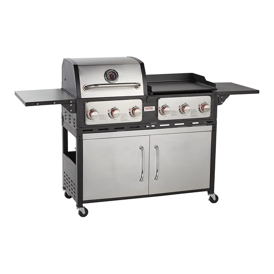
Outdoor Gourmet Gas and Griddle Combo
Model #: 157872
Please keep this instruction manual for future reference
Customer Service: (888) 922-2336, 7:00 am to 12:00 am daily CST
Live Chat on Academy Website (www.academy.com) 24/7 or email
customerservice@academy.com
(Made in China)
Advertisement

Related Manuals for Outdoor Gourmet 157872


Summary of Contents for Outdoor Gourmet 157872
- Page 1 Assembly Instructions & User’s Manual Outdoor Gourmet Gas and Griddle Combo Model #: 157872 Please keep this instruction manual for future reference Customer Service: (888) 922-2336, 7:00 am to 12:00 am daily CST Live Chat on Academy Website (www.academy.com) 24/7 or email customerservice@academy.com...
- Page 2 Table of Contents ..............12-23 ..............Operating Instructions 24-27 Trouble Shooting ............................28-30 ............Frequently Asked Questions ........Note: Before beginning assembly of product, make sure all parts are present. Compare parts with package content list and hardware contents. If any part is missing or damaged do not attempt to assemble the unit.
- Page 3 Page 3 of 32...
- Page 4 Griddle installation must conform with local codes,or in their absence,with either the National Fuel Gas Code,ANSI Z223.1/NFPA 54,Natural Gas and Propane Installation Code,CSA B149.1,or Propane Storage and Handling Code ,B149.2. Griddle,when installed,must be electrically grounded in accordance with local codes,or,in the absence of local codes,with the National Electrical Code,ANSI Z21.58-2018,or the Canadian Electrical Code,CSA 1.6 -2018.
- Page 5 from Place dust cap on cylinder valve outlet whenever the cylinder is not in use. Only install the type of dust cap on the cylinder valve outlet that is provided with the cylinder valve. Other types of caps or plugs may result in leakage of propane. 2.
- Page 6 1. Do not connect this grill to any unregulated sources of propane. 2. Before each use,check the gas hose for excessive abrasion or wear,or cuts.Replace a hose assembly showing those signs.The replacement hose assembly shall be that specified by the manufacturer.Inspect the hose assembly underneath the side burner and following the regulator hose up to its connection to the gas manifold assembly.
- Page 7 1. Ensure the LP cylinder valve and all burners are "OFF". 2. Ensure the LP cylinder is connected to the regulator. 3. If the information above is not followed exactly,a fire causeing death or searous injury may occur. 4. Mix a solution of 50% water and 50% liquid dish soap.Do not use any household cleaner solution. 5.
- Page 8 Page 8 of 32...
- Page 9 Parts List Tank Holder Bottom Shelf Back Panel Side Shelf 2PCS Directional Caster 4PCS Tank Barrier Bar Door (R) 1PC Fence Rail Back Side Bracket (R) 1PC Door (L) Handle Base 4PCS Door Handle 2PCS Body Side Table Connector (I) Side Table Connector (II) Back Side Bracket (L) 2PCS...
- Page 10 Exploded View Page 10 of 32...
- Page 11 Hardware BOLT M6 × 12 (49 pcs) BOLT M4 × 8 (2 pcs) BOLT M6 × 55 (4 pcs) MAGNET (1 pc) Ø1.5 x 28 COTTER PIN (4 pcs) BOLT M6 × 20 (8 pcs) GRIDDLE FOOT M6 × 30 (4 pcs) NUT M6 FLANGE LOCK (4 pcs)
- Page 12 Assembly Instructions Step 1: Assembly the Side Shelf (1) - 2 PCS to Bottom Shelf (2) - 1 PC using BOLTS M6 X 12 (A) - 4 PCS and M6 X 55 (C) - 4 PCS. Install Magnet (D) -1 PC on Bottom Shelf using BOLTS - 1 PC to the legs using BOLTS M4 X 8 (B) - 2 PCS.
- Page 13 Assembly Instructions Step 3: Install Back Shelf (4) - 1 PC using BOLTS M6 X 12 (A) - 7 PCS. Step 4: Install Directional Caster (5) - 4 PCS to side shelfs by twisting until tight. Turn over the bottom assembly when complete and lock casters to prevent from moving.
- Page 14 Assembly Instructions Step 5: Install Tank Barrier Bar (6) - 1 PC using BOLTS M6 X 12 (A) - 2 PCS. Step 6: Install Fence Rail (7) -1 PC to the - 1 PC to the legs using BOLTS side shelf using BOLTS M6 X 12 (A) - 4 PCS.
- Page 15 Assembly Instructions Step 7: Install Door Handle (11) - 2 PCS and Handle Base (10) - 4 PCS on the Door (8)(9) using BOLTS M6 X 12 (A) - 4 PCS. Step 8: Insert bottom-end of the door into the hole of the base on the bottom shelf as shown.
- Page 16 Assembly Instructions Step 9: Install Back Side Bracket (12)(13) -2 PCS to back side of cart using BOLTS M6 X 12 (A) - 4 PCS as shown. Step 10: Put the Body (14) - 1 PC onto the cart. Page 16 of 32...
- Page 17 Assembly Instructions Step 11: Lock Back Side Bracket to back side of body using BOLTS M6 X 12 (A) - 6 PCS as shown. Step 12: Install Side Table Connector (I) (15) - 2 PCS and Side Table Connector (II)(16) - 2 PCS on body using BOLTS M6 X 12 (A) - 8 PCS.
- Page 18 Assembly Instructions Step 13: Install Side Bracket (RF,LB)(17) - 1 PC and Side Bracket (LF,RB) (18) on Side Table (L)(19) - 1 PC using BOLTS M6 X 12 (A) - 4PCS. Repeat step with Side Table (R) (20) - 1 PC. Step 14: Install Side Table on body using BOLTS M6 X 20 (F) - 8 PCS.
- Page 19 Assembly Instructions Step 15: Place Flame Tamer (21) - 3 PCS into Gas side of body. Step 16: Place Cooking Grate (22) - 2PCS into body. Page 19 of 32...
- Page 20 Assembly Instructions Step 17: Assemble the Warming Grate (23) by inserting the top two ends to gas lid and bottom side to body. Secure the top part of warming grate with pre-assembled COTTER PIN (E) - 2 PCS. Step 18: Slide Drip Pan (24) - 1 PC into the Griddle Body.
- Page 21 Assembly Instructions Step 19: Assemble the Griddle Foot (G) - 4 PCS onto Griddle Top (25)- 1 PC using Screw Nuts (H) - 4 PCS. Put the Griddle Top onto the body. Step 20: Install the plate on the hose to the cart using BOLTS M5 X 10 (I) - 2 PCS as shown.
- Page 22 Assembly Instructions Step 21: Assemble the Oil Tray Handle (27) - 1 PC to Oil Tray (26) using BOLTS M6 X 12 (A) - 2 PCS. Slide the Oil Pan (28) - 1 PC underneath oil tray. Slide oil tray underneath left side of body.
- Page 23 FULLY ASSEMBLY Page 23 of 32...
- Page 24 Operating Instructions Your new gas grill operates on LP(Liquid Petroleum)Gas. It is odorless,colorless,and non-toxic when produced.You can smell LP gas as it have been given as odor similar to rotten cabbage for your safety. Your grill uses the newest and safest LP Gas Cylinder. In addition, the LP tank you use with your grill must meet the following requirements 1.
- Page 25 Operating Instructions LIGHTING THE MAIN BURNERS USING AUTOMATIC IGNITION 1. Open the lid. 2. Ensure all burner control knobs are in the “Off” position. 3. Turn on the LP gas by turning the hand wheel on the cylinder valve. 4. Turn one burner control knob marked with an igniter flame “ ”...
- Page 26 Operating Instructions Page 26 of 32...
- Page 27 Operating Instructions & Trouble Shooting Page 27 of 32...
- Page 28 Care and Maintenance GRIDDLE Cleaning Your Griddle 1. Do not clean any part of your barbecue griddle in a self-cleaning oven. 2. Do not use oven cleaners,abrasive kitchen cleaners,cleaners that contain citrus products,or mineral spirits. 3. Do not use any type of steel bristled brush. 4.
- Page 29 Care and Maintenance Griddle Top- The griddle top has a Non-Stick Property and will easy to clean and maintain.In order to keep the good performance of coating,please follow the below steps during cooking: - Please clean the griddle before use. - It is better to use warm/hot water only.
- Page 30 Care and Maintenance Page 30 of 32...
- Page 31 Frequently Asked Questions Page 31 of 32...
- Page 32 This product Page 32 of 32...
Need help?
Do you have a question about the 157872 and is the answer not in the manual?
Questions and answers