Table of Contents
Advertisement
Quick Links
Advertisement
Table of Contents

Subscribe to Our Youtube Channel
Related Manuals for Gooxi SY202-D12R


Summary of Contents for Gooxi SY202-D12R
- Page 1 SY202-D12R Dual-Socket High-Density Server Barebones User Manual Rev 1.0...
- Page 2 This chapter provides installation and maintenance instructions for each node on this high-density server . Chapter 5 Shelf Installation of Server System The necessary steps and precautions for using the SY202-D12R high-density server barebones system. Shenzhen Gooxi Information Security Co., Ltd.
-
Page 3: Table Of Contents
4.1 Node Installation......................... 35 4.2 Fan replacement & maintenance..................36 4.3 Installation of the hard disk....................38 Chapter 5 System rack installation......................39 5.1 Overview..........................39 5. 2 Steps to put the system on the shelf................... 39 Shenzhen Gooxi Information Security Co., Ltd. -
Page 4: Chapter 1 Product Introduction
2U Rackmount, 760mm* 444mm* 88mm 1.1.2 System Overview The SY202-D12R barebone system is a high-performance & high-density server barebone product. The product supports 2* simple-plug high-performance server nodes and 12* hot-swap hard disk modules in a 2U chassis height . -
Page 5: Motherboard Features
1. 2 Motherboard Features 1.2.1 Parameters: SY202-D12R with G1DCN-B single-socket server motherboard, is based on Intel X86 architecture design, adopts INTEL Grantley-EP platform, based on Intel PCH C612 chipset, with Intel latest generation Haswell CPU, compatible with Broadwell CPU to be released. -
Page 6: Server Chassis Features
Standard 1600W 1+1 redundant platinum-efficiency power supply, support hot-swap replacement; Input AC voltage: 100V~245V ; Output DC voltage: +12 V, +12 V_SB; Frequency: 47Hz~63Hz. 1. 3.3 Cooling system 4* 8038 fans (12V/Max 3.3 A ) Shenzhen Gooxi Information Security Co., Ltd. -
Page 7: System View
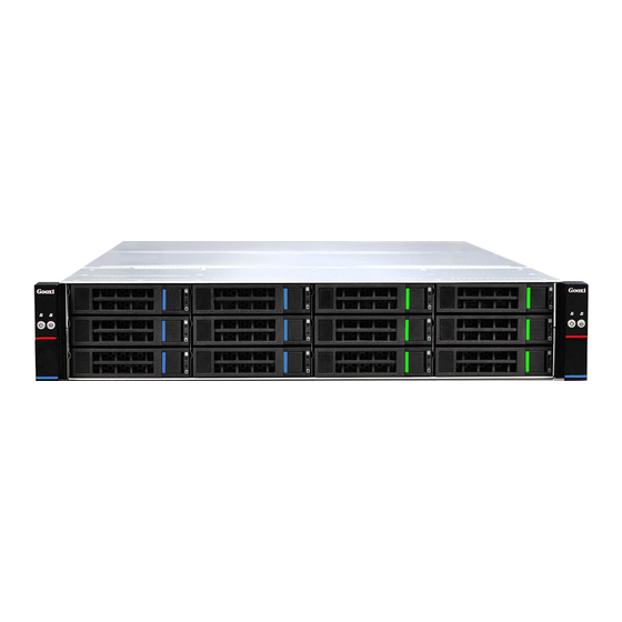
Power: up to 39.6W. Maximum RPM: 9000 +/- 10% RPM. Airflow: 3.754m³/min (132.6CFM), minimum 3.379m³/min (119.3CFM). Air pressure: MIN 460Pa, MAX 515.7Pa. 1. 4 System View 1. 4.1 Front view 1. 4.2 Rear view Shenzhen Gooxi Information Security Co., Ltd. - Page 8 Node 1 network port 2 is ⑫ connected normally Blue light is always Hard drive positioning indicator; ⑥ Yellow light is always Hard disk alarm indication Green light is always Hard disk presence indication ⑦ Shenzhen Gooxi Information Security Co., Ltd.
- Page 9 1. 4.3 Schematic diagram of the rear structure The above figure is a schematic diagram of the location of each node and power supply Shenzhen Gooxi Information Security Co., Ltd.
-
Page 10: Chapter 2 System Interface Introduction
Chapter 2 System Interface Introduction 2.1 Overview The main interfaces of the system are distributed on the motherboard. The following content mainly introduces the interface layout of the motherboard . 2.1.1 G1DCN-B MOTHERBOARD PHYSICAL PICTURE Shenzhen Gooxi Information Security Co., Ltd. - Page 11 2.1.2 G1DCN-B & MOTHERBOARD INTERFACE DEFINITION 1. S CHEMATIC DIAGRAM OF THE LOCATION OF THE MOTHERBOARD INTERFACE Shenzhen Gooxi Information Security Co., Ltd.
- Page 12 3Pin System Debug RS232 Connector JBAT1 CR2032 Battery Socket CPU1-DIMMA1 CPU1 memory channel A, 1st DIMM SLOT CPU1 memory channel A, 2nd DIMM CPU1-DIMMA2 SLOT CPU1-DIMMB1 CPU1 memory channel B , 1st DIMM SLOT Shenzhen Gooxi Information Security Co., Ltd.
- Page 13 USB3.0 Type Connector GPU_PWR1 8Pin GPU graphics card 1 power connector GPU_PWR2 6Pin GPU graphics card 2 power connector The Node ID LED is used to locate the node indicator System status indicator, reflecting system status Shenzhen Gooxi Information Security Co., Ltd.
-
Page 14: Motherboard Io Interface
. Its specific location on the motherboard is shown below. On the front of the motherboard, it corresponds to the ID button on the front panel of the server and is marked as D11 location : Indicator Shenzhen Gooxi Information Security Co., Ltd. - Page 15 The specific location is as follows. The position of D10 is the BMC LED. When the motherboard is powered on, the indicator is flashing; The indicator light is off when the power is not connected. Indicator Shenzhen Gooxi Information Security Co., Ltd.
- Page 16 2. 100M Link, orange long bright 3. 10M Link, LED off When there is data activity, the yellow light flashes Right LED When there is no data activity, the indicator does not light up Location map: Shenzhen Gooxi Information Security Co., Ltd.
- Page 17 When there is no data activity, the indicator does not light up Note : The indicators of the two network ports are the same. Schematic diagram of the location of the network port: 1GbE Port 2 1GbE Port 1 Shenzhen Gooxi Information Security Co., Ltd.
- Page 18 The graphics chip of the motherboard adopts AST2400. The AST2400 has a built-in PCIE VGA Controller, and a 15PIN VGA Connector is used to connect to the VGA display and output the host information. The location diagram is as follows: Shenzhen Gooxi Information Security Co., Ltd.
- Page 19 2.2.8 SATA INTERFACE The motherboard is designed with 4* SATA3.0 Connectors, all of which are from Intel PCH. The location diagram is as follows: Shenzhen Gooxi Information Security Co., Ltd.
- Page 20 The motherboard is designed to reserve 3PIN Power Connector for SATA DOM to access the power supply. The PIN is defined as follows: SATA DOM POWER Connector Pin Definition PIN sequence Description PIN1 PIN2 Ground PIN3 Ground Shenzhen Gooxi Information Security Co., Ltd.
- Page 21 CPU1_SLOT1 are all from CPU1, and the speed supports PCIE 3.0 8Gb/s; CPU1_SLOT2 is a X8 SLOT, and 8 PCIE LANs are from CPU1. Remark: CPU1_SLOT2 is not a standard PCIE SLOT and cannot be directly inserted into a standard PCIE device. Shenzhen Gooxi Information Security Co., Ltd.
- Page 22 DIMMB2 are Channel B sockets. Divided into two groups according to CPU type, each group as 8 DIMMs, CPU 1 and CPU 2 . Note: If only 1 DIMM is inserted into each Channel, it needs to be inserted into a slot away from the CPU. Shenzhen Gooxi Information Security Co., Ltd.
- Page 23 1st PIN. The 1st PIN is as follows: The red circle in the figure below shows the 1st PIN, which is indicated by a triangular arrow to correspond to the triangular arrow of the CPU. The schematic diagram of the CPU Socket location is as follows: Shenzhen Gooxi Information Security Co., Ltd.
-
Page 24: Connecting The Cables
G1DCN-B Single Board 2PIN use 2PIN serial Description Default setting number ME UPDATE No need to insert jumper caps ME Recovery No need to insert jumper caps JCMOS1 CMOS Clear No need to insert jumper caps Shenzhen Gooxi Information Security Co., Ltd. -
Page 25: Power Module Indicators
The power module is operating normally always on Orange light is Power module alarms, possibly over temperature, over always on voltage, over current, or fan failure AC power is not connected to the power module Shenzhen Gooxi Information Security Co., Ltd. -
Page 26: Chapter 3 Detailed Node Installation
CPU, heat sink and memory. Diagram of the rear interface of the node is as follows: PCI-E expansion slot2 PCI-E expansion slot1 Node snap After the node is extracted, the internal schematic picture is as follows: Shenzhen Gooxi Information Security Co., Ltd. -
Page 27: Installation Of Cpu
2. Please make sure that the processor specification purchased is of the supported type for this motherboard. 3. If you buy the CPU in bulk , please make sure your CPU is using a Gooxi certified heat sink. Detailed steps to install LGA 2011 processor: 1. - Page 28 CPU and the socket. Triangle mark 5. Gently close the upper cover of the installing box. Warning : Do not force the upper cover of the installing box to close, as doing so may damage the CPU. Shenzhen Gooxi Information Security Co., Ltd.
- Page 29 Return Merchandise Authorization (RMA), and we can repair and warranty the product. protective cover 7. Push down the left fixing wrench (L) and insert it under the fixing tab (M). Shenzhen Gooxi Information Security Co., Ltd.
-
Page 30: Installation Of Cpu Heat Sink
5. Reverse the sequence of this process to remove the heat sink. 3.3 Memory installation CAUTION: When installing or removing DIMM memory modules, take extra care to prevent any possible damage to the DIMM or their respective sockets. Shenzhen Gooxi Information Security Co., Ltd. - Page 31 Notch Demonstration diagram to insert a memory stick: Removal: Use your thumb to gently push the release tabs near the ends of the memory module socket. This should release the memory from the socket. Shenzhen Gooxi Information Security Co., Ltd.
- Page 32 EMORY SETTING RULES Note : 1. Refer to the memory compatibility list on Gooxi's official website for selection. 2. To install a memory module in a single CPU configuration, please install the memory module in the A1 or B1 slot.
-
Page 33: Installation Of Expansion Cards
3.4 Installation of expansion cards This system node supports the expansion of 2* PCI-E X8 expansion cards or a full-height PCI-E X16 expansion card, or a GPU, all of which require the use of Gooxi dedicated Riser cards. This section introduces three cases : 3.4.1 The steps for installing 2 PCI-E X8 expansion cards are as follows :... - Page 34 3. Install the assembled Riser card and expansion card back to the node, as shown in the following figure: Note: Make sure that the Riser card and expansion card are inserted in place. Shenzhen Gooxi Information Security Co., Ltd.
- Page 35 3.4.2 Steps for installing PCI-E X16 expansion card( Gooxi X16 Riser card required ): 1. Remove the Riser card from the node, the steps are as follows: 2. Insert the expansion card into the Riser card. The detailed assembly steps are as follows: 2.
- Page 36 3.4.3 Steps to install 1 GPU are as follows : 1. Remove the Riser card from the node, the steps are as follows: 2. Insert the GPU into the Riser card. The detailed assembly steps are as follows: Shenzhen Gooxi Information Security Co., Ltd.
- Page 37 3. Install the assembled Riser card and GPU back to the node , as shown in the following figure: Note: Make sure that the Riser card and expansion card are inserted in place. Shenzhen Gooxi Information Security Co., Ltd.
-
Page 38: Chapter 4 Barebone Installation & Maintenance
, as shown in the figure : Final installation effect is as follows: Installation complete picture The reverse operation is the step of dismantling a node . Shenzhen Gooxi Information Security Co., Ltd. -
Page 39: Fan Replacement & Maintenance
The system divides the 4* 8038 fans into two groups, which is convenient for maintenance. First, all the nodes need to be removed, as shown in the following figure: Unscrew the top and side screws of the upper cover, as shown below: Shenzhen Gooxi Information Security Co., Ltd. - Page 40 Remove the fan module, replace it and put it back into the chassis according to the original method, as shown below: Shenzhen Gooxi Information Security Co., Ltd.
-
Page 41: Installation Of The Hard Disk
4.3 Installation of the hard disk Whole system supports 1 or 2* 3.5/2.5-inch hard disks, and the installation method of each hard disk is the same, as shown in the following figure: ① ② Installation complete picture Shenzhen Gooxi Information Security Co., Ltd. -
Page 42: Chapter 5 System Rack Installation
Chapter 5 System rack installation 5.1 Overview This chapter describes the use of SY202-D12R high- performance dual-socket server barebone progress. Select an appropriate location on the rack to place the server system . This location should meet the following conditions: a clean and well-ventilated area with little or no dust, be careful to avoid high temperature, electrical noise, and electromagnetic interference. - Page 43 ③ Install the drawn inner rail on the chassis, as shown in the figure below: ① Shenzhen Gooxi Information Security Co., Ltd.
- Page 44 ② ③ Fix the guide rails into the cabinet, and then pull out the middle rails. Shenzhen Gooxi Information Security Co., Ltd.
- Page 45 ① ② Raise the entire system, place it on the guide rails horizontally and push it into the Shenzhen Gooxi Information Security Co., Ltd.
- Page 46 As shown below: Press down the right buckle Lift up the left buckle Shenzhen Gooxi Information Security Co., Ltd.
- Page 47 Memory Maximum 512G DDR4-1600/1866/2133 ECC-RDIMM, 1024G support type ECC-LRDIMM, capacity supports 8 GB, 16GB, 32GB, 64GB System hard Intel ® RSTe supports software RAID 0, 1, 10 & 5 ( for windows only) Shenzhen Gooxi Information Security Co., Ltd.
- Page 48 Microsoft Hyper-V (Target) Virtualization Citrix Xen Server (Target) Linux Kernel Virtual Machine (Target) System ambient temperature Operating temperature: 10℃~35℃; non-operating temperature: Temperature -40℃~70℃ Humidity Operating humidity: 35%~80%; Non-operating humidity: 20%~90% Safety certification Certification CE, ROHS Shenzhen Gooxi Information Security Co., Ltd.
Need help?
Do you have a question about the SY202-D12R and is the answer not in the manual?
Questions and answers