
Related Manuals for Gooxi SY4104G-G4


Summary of Contents for Gooxi SY4104G-G4
- Page 1 SY4104G-G4 机架式服务器用户手册 SY4104G-G4 Rackmount Server User Manual 文档版本:V1.0 Document version: V1.0 发布日期:2024/2/22 Release date: 2024/02/22 Shenzhen Gooxi Information Security Co., Ltd.
-
Page 2: Statement
Gooxi provides this user manual "as is" and to the extent permitted by law, makes no express or implied warranties or guarantees, including but not limited to merchantability, fitness for a particular purpose, non-infringement of any rights of others, and any warranties or guarantees regarding the use or inability to use this user manual. -
Page 3: Foreword
Foreword This manual is the product technical manual for the SY4104G-G4 rackmount server, mainly introducing and explaining the appearance, structure, hardware installation, and basic configuration of this product. This manual is intended for reference by professional technical personnel. Installation and maintenance of this product should only be carried out by experienced technical personnel. -
Page 4: Table Of Contents
Contents Statement..............................1 Foreword..............................2 1. Product Introduction ..........................5 1.1 Product Overview ........................5 1.2 Product Structure .........................6 1.3 Logical Structure .........................7 1.4 Product Specifications .........................8 2. Hardware Description ..........................9 2.1 Front Panel ..........................9 2.1.1 Appearance ........................9 2.1.2 Indicator lights and buttons ..................9 2.1.3 Interface ........................ - Page 5 3.2.4 Install the heatsink fan cover ..................28 3.2.5 Memory installation ....................29 3.2.6 M.2 card installation ....................30 3.2.7 GPU card installation ....................30 3.2.8 Server slide rail installation ..................31 4. Configuration Instructions ........................34 4.1 Initial Configuration .......................34 4.1.1 Power on and start .......................34 4.1.2 Initial data ........................
-
Page 6: Product Introduction
1. Product Introduction 1.1 Product Overview SY4104G-G4server is a 4U 4-GPU dual-socket rackmount server designed by the company to meet the demands of image processing, cloud computing, inference, and telecommunications applications. It is based on the design of the 4th/5th generation Intel®... -
Page 7: Product Structure
Rear view 1-2 1.2 Product Structure The components of the SY4104G-G4 server are as shown in the following diagram: Structure diagram 1-3 Name Name Front Hard Drive Rear Module Front Hard Drive Bracket Power Supply Module Front Backplane Assembly Rear Fan... -
Page 8: Logical Structure
1.3 Logical Structure The logic of the SY4104G-G4 server is as shown in the following diagram: Motherboard logic block diagram 1-4 CPU supports 2 Intel® Xeon® Scalable processors (Sapphire Rapids/Emerald Rapids) with LGA4677 socket, TDP power consumption of 350W. -
Page 9: Product Specifications
1.4 Product Specifications Product Series SY4104G-G4 4U 12-bay Product Type 760mm*444mm*176.5mm(D*W*H) System Size Supports 2 Intel® Xeon® Scalable processors Processor 16 DDR5 slots supporting DDR5 RDIMM 4400/4800/5600MHz, Memory maximum supported frequency of 5600MHz; maximum capacity per module is 64GB Internal Storage 3 MiniSAS HD interfaces, 2 SATA DOM interfaces, 2 PCIe 5.0 M.2... -
Page 10: Hardware Description
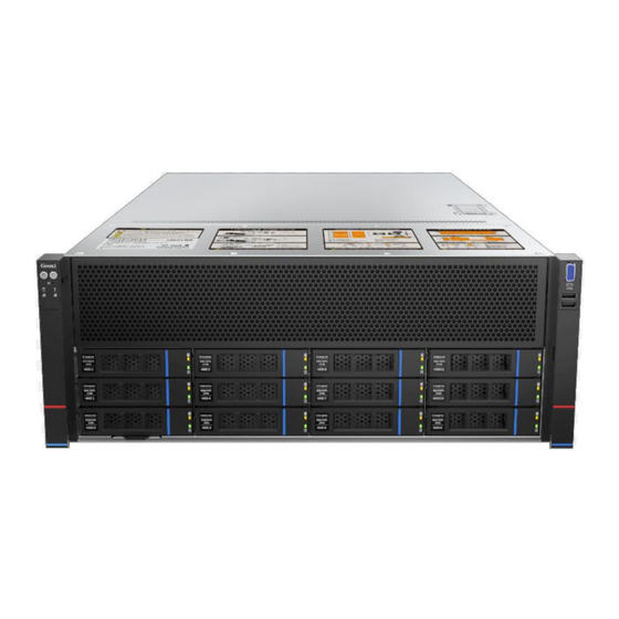
2. Hardware Description 2.1 Front Panel 2.1.1 Appearance 12x3.5-inch hard drive configuration Figure 2-1 Name Name Right Ear Integrated Left Ear Integrated Assembly Assembly Front Panel Hard Drive Module Table 2-1 2.1.2 Indicator lights and buttons Figure 2-2... - Page 11 Indicator light/button Indicator light/button GOOXI Logo Hard Drive Activity Indicator Power On/Off System Alarm Indicator Button/Indicator UID Button/Indicator Network port 1 connection status indicator light Network port 2 connection Reset Server Button status indicator light LED status description Indicator Logo...
-
Page 12: Interface
Network port 2 Indicator lights for Ethernet Port 2: connection Green (steady on): Indicates normal network port status indicator connection. Off: Indicates the network port is not in light use or is faulty. Explanation: Corresponds to the two network ports on the motherboard. Table 2-2 2.1.3 Interface Interface location... - Page 13 Figure 2-4 Name Name Power Module USB 2.0 Interface PCIe Interface VGA Interface Riser Module (optional) USB 3.0 Interface Rear Fan Module Management Port (optional) RJ45 Gigabit Ethernet Port Table 2-5 Note: The rear window of this product can be customized according to requirements. ...
-
Page 14: Indicator Lights And Buttons
2.2.2 Indicator lights and buttons Rear Panel Indicators Figure 2-5 Name Name Power module indicator light BMC reset button Data transmission status Connection status indicator light indicator light Data transmission status Connection status indicator light indicator light COM port UID button Table 2-7 Description of Power Module Indicators... -
Page 15: Processor
When configuring with 1 processor, it must be installed in the CPU 0 position. Processors installed in the same server must have the same model. For specific optional system components, please consult Gooxi sales. Processor positions are as shown in the diagram below: ... -
Page 16: Memory Compatibility Information
Figure 2-7 2.4.2 Memory Compatibility Information The motherboard supports DDR5 RDIMM memory with memory frequencies of 4400/4800/5600MHz. Note: The same server must use the same model of DDR5 memory, and all memory modules must operate at the same speed. The speed value is the minimum of the following: The memory speed supported by the specific CPU. -
Page 17: Storage
2.5 Storage 2.5.1 Hard drive configuration Maximum Front Maximum Rear Configuration Description Hard Drive Qty Hard Drive Qty Front Hard Rear Module: SAS hard Drive: (12x3.5") (2x2.5") x 2 drives require the selection 12x3.5-inch The slots from of a SAS Hard Drive slot 0 to slot 11 Supports... -
Page 18: Power Supply
When configuring 2 power modules, supports 1+1 redundant backup. Power modules in the same server must have the same model. For specific optional system accessories, please consult Gooxi sales. The power module locations are as shown in the following diagram: ... -
Page 19: I/O Expansion
Figure 2-12 2.8 I/O Expansion 2.8.1 PCIe slot location Figure 2-13 Figure 2-14 The slots provided by the motherboard are Slot1, 2, 3, 4, 5, 6, 7, 8, 9, while the slots provided by Riser1 module are Slot10, 11. When installing double-width GPU cards, they must be installed in slots 2, 5, ... -
Page 20: Pcie Slot Description
6, 9. Slots 1, 4, 8 are not available at this time. 2.8.2 PCIe slot description When CPU1 is not in place, the corresponding PCIe slot is not available. Subordinat PCIe slot PCIe standard Bus bandwidth Slot size e CPU Half height Slot 1 CPU0... -
Page 21: Pcba
Figure 2-16 2.9 PCBA 2.9.1 Motherboard Motherboard Figure 2-17... - Page 22 Name 1、8 System fan 4-pin connector UID button COM port BMC_LAN/USB3.0 Rear VGA Rear USB2.0 RJ45 Gigabit network port CPU1 PCIE5.0 Port0(lane8~15) X8 MCIO connector CPU1 PCIE5.0 Port0(lane0~7) X8 MCIO connector 12Pin hard drive backplane power connector PCIE CPU0 M.2 connector 4-pin rear backplane power connector NIC power connector 8Pin power board connector...
-
Page 23: Hard Drive Backplane
2.9.2 Hard drive backplane 12×3.5-inch Backplane TOP surface Figure 2-18 Description Function Supports PCIe×4 and SAS/SATA U.2 SFF-8639 U.2 hard drive interface, used connect connector HDD/SSD/NVME Table 2-13 Bottom surface Figure 2-19 Description Function Temperature-controlle 1、2、3、4 used for 4-pin fan interface d fan socket providing SAS/SATA×4... - Page 24 Figure 2-20 Description Function 1.Maximum support for 12G/b SAS/SATA hard drive SAS hard drives. connector 2.Maximum support for 6G/b SATA hard drives. Table 2-15 Bottom surface Figure 2-21 Description Function 1、2 7-pin SATA interface SATA disk signal wire interface Backplane power transmission 5-pin interface...
-
Page 25: Riser Card
TOP surface Figure 2-22 Description Function SFF-8639 U.2 hard drive Supports PCIe x4 U.2 interface, connector used for connecting NVMe SSDs Table 2-17 Bottom surface Figure 2-23 Description Function providing PCIe×8 interface for connecting MCIO connector to CPU and NVME SSD JTAG debugging used for CPLD programming and version... - Page 26 Figure 2-24 x16 to x8 (x16 slot) + x8 adapter card Installed in Riser1 position, providing PCIe slots as Slot10 and Slot11. Figure 2-25...
-
Page 27: Installation Instructions
3. Installation Instructions 3.1 Chassis Top Cover Installation Step 1: Lift the slot at the opening position, push and lift it in the direction indicated by the diagram. Figure 3-1 3.2 Installation of Accessories 3.2.1 Remove the heatsink fan cover Step 1: Unscrew the two screws on the heatsink fan cover (keep the screws), ... -
Page 28: Cpu Installation
Figure 3-2 3.2.2 CPU installation Step 1: Align the triangle mark on the CPU with one end of the retention bracket as shown in the diagram, press down to install the CPU onto the retention bracket, then press down on the retention bracket to secure the CPU onto the heatsink (the heatsink has been evenly coated with approximately 0.4ml of thermal grease). -
Page 29: Heatsink Installation
3.2.3 Heatsink installation Step 1: Remove the processor cover. Figure 3-4 Step 2: Install the CPU and heatsink onto the motherboard. Align the heatsink mounting screws on the heatsink base with the fixed screws on the CPU socket, and tighten the heatsink mounting screws in the indicated sequence. -
Page 30: Memory Installation
Figure 3-6 Note: The pins on the motherboard are extremely fragile and can be easily damaged. To avoid damaging the motherboard, do not touch the processor or the processor socket pins. 3.2.5 Memory installation The 8 memory slots controlled by CPU0 on the motherboard are: DIMM_A1, DIMM_B1, DIMM_C1, DIMM_D1, DIMM_E1, DIMM_F1, DIMM_G1, DIMM_H1. -
Page 31: Card Installation
Figure 3-8 Note: Please use memory modules with the same CAS latency value on this motherboard. We recommend using memory modules of the same capacity, frequency, and manufacturer for optimal compatibility. It is important to note that: In the same channel, memory modules with larger capacities must be installed in the first slot. -
Page 32: Server Slide Rail Installation
Figure 3-10 3.2.8 Server slide rail installation Step 1: Prepare two slide rails and pull out the inner rail. Figure 3-11 Step 2: Fasten the inner rails to the sides of the chassis. Figure 3-12 Step 3: Install the outer rails on the cabinet brackets and secure the screws. ... - Page 33 Figure 3-13 Note: When installing the guide rail, align it with the U-mark, and push it into place until you hear a click sound. Secure it firmly using M5 screws. Step 4: Align the chassis with the inner rails installed with the outer rails for ...
- Page 34 Figure 3-15 Note: During equipment maintenance, it is necessary to loosen the panel screws and pull the chassis lightly. Do not push or pull the chassis at random speed to avoid damage to the equipment.
-
Page 35: Configuration Instructions
4. Configuration Instructions 4.1 Initial Configuration 4.1.1 Power on and start Before powering on, it is necessary to ensure that all configurations of the server are installed in accordance with the corresponding specifications and standards, and keep the server turned off but not unplugged from the power supply. - Page 36 Figure 4-1 State After G3 The menu options for setting the state after entering G3 status are: S0: Power on and start up directly S5: You need to press the Power button to turn on the power leave power state unchanged: Leave the power state unchanged . Default: S5 State Log in to the iBMC management interface to perform remote power-on and ...
-
Page 37: Initial Data
Figure 4-2 For detailed usage of BMC and BIOS, please refer to the corresponding user manual. 4.1.2 Initial data BMC default account: admin BMC default password: Gooxi@123. BMC default address: 192.168.100.1 BIOS Default Password: None 4.1.3 Configure BIOS Press the <DEL>... -
Page 38: Configure Bmc
Figure 4-3 The Main interface contains the basic information of the BIOS system, such as the BIOS version number, CPU model, memory capacity, and the system time can be set. For detailed instructions, please refer to the "BIOS User Manual". Navigation key description: ... - Page 39 After the server is powered on, turn it on. Pay attention to the POST process when starting the server. In the lower left corner of the logo screen, the IP address is displayed. After the server powers on, pay attention to the POST process. Press the ...
- Page 40 port. The displayed information includes the current IP configuration method, BMC IP, subnet mask, MAC address, router IP, and router MAC. BMC Dedicated Management Channel Configuration Address source Configure the BMC IP address allocation mode, the menu options are: ...
- Page 41 BMC Dedicated Management Channel IPV6 Support Choose whether to support IPV6, the menu options are: Enabeld: support IPV6 Disabled: does not support IPV6 Default: Enabeld When changing from "Unspecified" to other parameters, saving and rebooting will result in the options reverting to the "Unspecified" value. There is no need to configure the BMC IP during every startup process.
- Page 42 Figure 4-6 This page sets the IP address of the BMC management network port.
-
Page 43: Appendix
If the above steps do not resolve the issue, try replacing the monitor with a known working one to confirm if the original monitor is faulty. If the issue persists, please contact Gooxi's customer service department for resolution. Front Panel Indicator Lights Alarm Refer to the instructions in the manual to determine the specific alarm information indicated by the front panel lights and buttons. - Page 44 Set static or dynamic IP and ensure ping connectivity. If the web interface does not open, try using a newer version of Internet Explorer. If the problem is not resolved, please contact Gooxi’s customer service department for further assistance and resolution.
-
Page 45: Scrap Recycling
6. Scrap Recycling For environmental protection and resource reuse, we earnestly ask you to properly handle discarded server products. Before discarding the server, we recommend that you completely demagnetize the storage media, clear data, and physically destroy them to ensure that your personal data is not leaked.
Need help?
Do you have a question about the SY4104G-G4 and is the answer not in the manual?
Questions and answers