Table of Contents
Advertisement
Quick Links
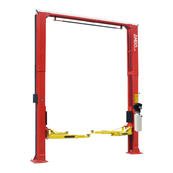
TWO POST LIFT
Cargo Claims
If there is any missing or damaged
product during transportation, the
buyer must notate on the shipping
paperwork or refuse the shipment.
NOTATE ALL DAMAGE OR REFUSE
DAMAGED SHIPMENT!
Model:OH-9
△
DANGER
!
Read the entire contents of this manual before
using this product. Failure to follow instructions
and safety precautions could result in serious
injury or even death. Make sure all other
operators also read this manual. Keep this
manual near the machine so that it can be seen
by all users. By proceeding with installation and
operation, you agree that you are fully
understand the contents of this manual and take
full responsibility for the use of the product.
Advertisement
Table of Contents

Related Manuals for AMGO OH-9


Summary of Contents for AMGO OH-9
- Page 1 TWO POST LIFT Model:OH-9 △ DANGER Read the entire contents of this manual before using this product. Failure to follow instructions and safety precautions could result in serious Cargo Claims injury or even death. Make sure all other operators also read this manual. Keep this...
-
Page 2: Table Of Contents
CONTENTS PROFILE ..................1 SAFETY INSTRUCTION ..............3 I. PRODUCT FEATURES AND SPECIFICATIONS ........5 II. INSTALLATION REQUIREMENT ............. 7 III. INSTALLATION STEPS ..............10 IV. EXPLODED VIEW ..............32 V. TEST RUN ................39 VI. OPERATION INSTRUCTIONS ............. 41 VII. MAINTENANCE SCHEDULE ............42 VIII. -
Page 3: Profile
PROFILE This instruction manual is specially prepared for you. Your new lift is the product of over a decade of continuous research, testing and development and is the most technologically advanced lift on the market today. Please make sure to read through this manual before operating the lift. Record the information on the nameplate label here: Model No.: Serial No.:... - Page 4 SAFETY WARNING LABEL Fig. 1...
-
Page 5: Safety Instruction
SAFETY INSTRUCTION In order to properly maintain your product and ensure operator safety, it is the responsibility of the product owner to read and follow these instructions! 1. Ensure product installation complies with all applicable local regulations and rules, such as Occupational Safety and Health Administration regulations and electrical codes. - Page 6 15. Warning! There is a risk of explosion. There are parts in the equipment that produce arc light and spark. Do not be exposed to easy gas. This machine should not be placed in the lounge or basement. 16. Maintain with care. Keep the machine clean for better and safer operation. Perform proper lubrication and maintenance procedures according to the manual.
-
Page 7: Product Features And Specifications
Lifting Lifting Overall Without Include Without Include Model Overall Height Motor Capacity Time Width extension extension extension extension Height adapter adapter adapter adapter OH-9 9000lbs 71 1/2" 80 1/2" 69 5/8" 78 5/8" 143 1/8"/ 151" 135" 3 9/16" 2.0HP... - Page 8 Arm Swings View Drive-in direction 135" Fig.3 Attention! Please make sure to place the arms in correct position before car drive in ! Fig.4 △ CAUTION When driving the vehicle, stay in the middle between the columns. If you hit any part of the lift, you could damage the car or lift.
-
Page 9: Installation Requirement
II. INSTALLATION REQUIREMENT A.TOOLS REQUIRED Rotary Hammer Drill (Φ19) Carpenter’s Chalk Hammer Screw Sets Level Bar Tape Measure (7.5m) Adjustable Spanner (12") Pliers Lock Wrench Wrench set # # # # # ... - Page 10 B. Equipment storage and installation requirements. 1.Store the equipment in a dry, non-moldy, non-flammable environment. 2.The lift is only approved for indoor installation and use, and outdoor installation is prohibited. 3.When installing the device, take safety precautions according to the instructions to avoid device damage.
- Page 11 Concrete intensity must be 3000psi minimum Fig.8 E. POWER SUPPLY 1. You are required to use a licensed and qualified electrician for the installation process. 2. The power supply capacity must be more than 3.0HP, with a cord larger than 12AWG, and must be properly grounded.
-
Page 12: Installation Steps
III. INSTALLATION STEPS Location of installation 1. Installation space: Ensure there is enough space for the lift. Accurately measure the front, back, side and top mounting dimensions and refer to the below figure data(See Fig. 9). 2. Overhead obstacle: Check for overhead obstacles, such as building supports, heaters, lights, wires, and low ceilings, etc.. - Page 13 B. Use a carpenter’s chalk line to establish installation layout of base-plate (See Fig.10). Click a line Fig. 10 135" Check the parts before assembly. Packaged lift and hydraulic power unit ( See Fig. 11). Fig. 11 2. Move aside the lift with fork lift or hoist, open the package , move aside the arms and parts box, and check the parts according to the shipment list.
- Page 14 4. Move aside the parts and check the parts according to the parts list. (See Fig. 13 & 14) Parts box (50) Shipment list Fig. 14 Fig. 13 5. Check the parts of the parts bag 1 &2 according to parts bag list (See Fig.
- Page 15 This lift is designed with 2-section columns, the height is adjustable according to the ceiling height, so connection positions of the inner column and outer column would be different. 1. OH-9 requirement: Ceiling height over 151 5/8", can be both low setting/high setting; Ceiling height between 143 3/4"-151 5/8", only available low setting;...
- Page 16 Note: a. for high setting, connect the lower hole of the outer columns (see Fig.17). b. for low setting, connect the upper hole of the outer columns (see Fig.18). High setting Fig.17 Low setting Fig.18...
- Page 17 Erect the columns, install anchor bolts, check the columns plumbness with level bar, and adjust with shims if the columns are not vertical. Do not tighten the anchor bolts. 112 3/16” 135” Note: Minimum embedment of anchors is 3 9/16” Bolting Drilling Cleaning...
- Page 18 Install top beam 1. Hook the top beam(with limit switch) on the power side outer column, align the holes and install the bolts. (See Fig. 20) Note: The top beam with limit switch should be installed on the power side column. Fig.
- Page 19 2. After install the other top beam on off side outer column, bolt both top beams and tighten all the bolts. Finally tighten the anchor bolts. (See Fig. 21) Fig.
- Page 20 Install control bar for limit switch (See Fig.22) Off side Loosen the bolt slightly, adjust the Power side distance between the two control bar support brackets till the control bar can rolls smoothly, then tighten the bolts. Limit switch Control bar Hex bolt M8*35mm Hex bolt (M8*16mm) with locker washer...
- Page 21 Exploded view of safety device Fig. 24 Power side Safety Device 76B 76C Fig. 25 Off side Safety Device...
- Page 22 Install cables. Raise up the carriages and lock at the same level of safety lock. Low setting cable connection (See Fig. 26). Note: pass the cable through the inside of carriage. Low setting Cable1 Cable2 Cable2 Fig. 26...
- Page 23 2.High setting cable connection 2.1. Pass the cable from the bottom of the carriage to the carriage window, then screw up the 2 cable nuts together. (See Fig. 27). High Setting Screw the two cable nuts Cable Connecting direction Cable Connecting Fig.
- Page 24 2.2 Cable connection for high setting (See Fig. 28). Cable 2 Cable 1 Cable 2 Fig. 28...
- Page 25 Install hydraulic power unit and oil hose assy. 1. Oil-line connection diagram. (See Fig.29) Fig.29...
- Page 26 2. Follow these step to connect the oil hose of power unit. Left oil outlet port Right oil outlet port Socket plug B. Assemble 90 fitting of power unit, and A. Disassemble the socket plug. connecting the oil hose. Plastic red plug D.
- Page 27 M. Install protective cover and cable limit bracket (Fig.31) Tighten the M6*40 round head bolt 1. Screw on round head bolt M6*40 a little. 2. Install protective cover, then tighten the round head bolt Only use for high setting Install protective cover to fix oil hose and bellow pipe Fig.
- Page 28 N. Install lock release cable (See Fig. 32) Lock release cable across outside of wire clamp Lock release cable Pass the cable through pulley bracket Limit switch wire Oil hose Finally connect the cable to power side safety device. Install the cable initially from off side safety device.
- Page 29 O. Install safety device protective cover. Round head bolt M6*8 with flat washer Fig.33...
- Page 30 P. Install lifting arms according to figure 34, fix the arm pins with springs, and then install toe guards. Engagement of moon gear and arm lock: Lower the carriages down to the lowest position, use socket head wrench to loosen the socket bolt follow the arrow direction to adjust the moon (See Fig.
- Page 31 Q. Tighten all the hydraulic fittings, and fill the reservoir with hydraulic oil. Note: In consideration of Hydraulic Power Unit’s durability and keep the equipment running in the perfect condition, please use Hydraulic Oil 46#. R. Install electrical system Connect the power source on the data plate of power unit. Note: Must install limit switch;...
- Page 32 Power supply wires Remove this wire Limit switch wire Fig. 40 Fig.41...
-
Page 33: Exploded View
IV. EXPLODED VIEW Model: OH-9 Fig. - Page 34 PARTS LIST Item Parts# Description Qty. 10206019 Clip ring φ19 10209012 Snap ring φ3.2 10209128 Flat washer φ20 1002011001 Bronzed bush φ22*φ19*14 1102011001 Pulley φ80*φ22*15 11206202 Power side colum 10209003 Hex bolt M8*25 10209004 Rubber ring φ8*20*3 10209005 Nylok nut (M8) 11217436 Safety device spacer φ27*15 11217006...
- Page 35 Item Parts# Description Qty. 11217046-01 Arm lock bar (right) 11217168 Arm pin 10520023 Clip ring φ38 10206190 Tool Tray (Short) 11206191 Toe Guard 10209019 M6*16 flat screw 10209018 Protective Rubber 11279004 Carriage 10279010 Front right arm assy. 10201046A Rubber pad assy. 10420138 Socket bolt M6*16 10209134...
- Page 36 Item Parts# Description Qty. 10217030 Spring φ2.0*120° 11217009 Safety device 10217010 Hex bolt M6*40 11217029-01 Small pulley bracket 11217031 Cam lock 10217032 Cable connecting pin 10217033 Nylok nut 11203778-01 Protective cover L=61 7/16” 10206079 Round head bolt M6*40 11206203 Off side column 11209051B Stackable adaptor (1.5”) 11209052B...
- Page 37 4.1 Rear arm(10279011): Fig. 45 Item Parts# Description Qty. 10206048 Socket bolt M10*30 φ10 lock washer 10209039 φ10 flat washer 10209022 11206049 Moon gear Outer arm 11206192 Round head bolt M8-12 10201149 11206193-01 Inner arm 4.2 Front-left arm(10279009): Fig. 46...
- Page 38 Item Part# Description QTY. 10206048 Socket bolt M10*30 10209039 Lock washer φ10 10209022 Flat washer φ10 11206049 Moon gear Outer arm 11206182 Middle arm 11206712-01 Round head bolt M8*12 10201149 Inner arm 11201049A-01 4.3 Front-right arm(10279010): Fig. 49 Fig. 47 Item Part# Description...
- Page 39 4.4 Cylinders (10217056) Fig. Parts for Cylinder Item Parts# Description Qty. 30-1 10209069 O ring 30-2 10209070 Bleeding plug 30-3 10209071 Support ring 30-4 10209072 Y Ring 30-5 10209073 O ring 30-6 11209074 Piston 30-7 11209075 O ring 30-8 11217076 Piston rod 30-9 11209077...
-
Page 40: Test Run
4.5 Illustration of hydraulic valve for hydraulic power unit Oil return port Relief valve Release valve Throttle valve Handle of Release Oil outlet port valve Check valve Fig. V. TEST RUN 1. Adjustment of sync cable (See Fig. 50) Use an open spanner to clamp the cable joint, and use a ratchet wrench to tighten the cable nut until the two sync cables are adjusted to a certain tension force and are consistent. - Page 41 Exhaust air from oil cylinder This hydraulic system is designed with a bleeding plug, located Bleeding Plug at the top of the cylinder, raise the carriages to about 1 meter height and loose the bleeding plug, the air would be bled automatically, then tighten the plug after bleeding air, the lift would work stably and smoothly, otherwise, repeat bleeding air.
-
Page 42: Operation Instructions
Hydraulic Schematic Diagram 1. Filter 2. Gear pump 3. Motor 4. Relief valve 5. Release valve 6. Check valve 7. Throttle valve 8. Cylinder Fig. △ WARNING Do not lift vehicles that exceed the rated capacity of the lift. Please do not release the safety handle until the lift safety lock is locked. -
Page 43: Maintenance Schedule
7. Push UP button until the lifting pads contact underside of vehicle totally and recheck lifting points; 8. Continue to raise the lift slowly, ensure the balance of vehicle, lift the vehicle to the desired height, release the UP button; 9. - Page 44 4. Check Rubber Pads and replace as necessary; 5. Check Safety device and make sure proper condition; 6. Check limit switch and make sure in proper condition; 7. Check the oil level of power unit and ensure is normal; 8. Check the moon gear and arm lock and ensure in proper condition. Oil cylinder maintenance: In order to extend the service life of the oil cylinder, please operate according to the following requirements.
-
Page 45: Trouble Shooting
VIII.TROUBLE SHOOTING TROUBLE CAUSE REMEDY 1. Button does not work 1. Replace button 2. Wiring connections are not in good 2.Repair all wiring connections condition Motor does not 3. Motor burned out 3. Repair or replace motor 4. Height limit switch is damaged 4. -
Page 46: Car Lift Safety Tips
IX. CAR LIFT SAFETY TIPS Put these safety tips in a place where you can always alert the operator. Please reference to the lift manufacturer’s manual for specific information about the lift. 1.Check the lift daily. If the machine breaks down or has damaged parts, do not operate, and use the parts of original equipment to repair. - Page 47 Manual No.: 72228006 Revision Date: 2024/04...
Need help?
Do you have a question about the OH-9 and is the answer not in the manual?
Questions and answers