Advertisement
Advertisement

Related Manuals for AMGO BP-9X


Summary of Contents for AMGO BP-9X
- Page 1 TWO POST LIFT Model: BP-9X...
-
Page 2: Table Of Contents
CONTENTS Products features and specification…………………………………………………………...1 Installation requirement..............3 Steps of installation ................4 Explosive view................17 Test run……………................19 Operation instruction...............21 Maintenance...................21 Trouble shooting………………………………………………………………………………………….22 Part list………………………………………………………………………………………………………..23... -
Page 3: Products Features And Specification
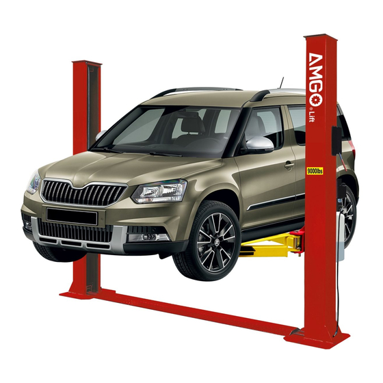
Minimum Gross Model Style Lifting Height Between Motor Capacity Time Height Width Pad Height Weight Columns Floor-plate 4000kg 1940-2169mm 2841mm 3460mm 2850mm 706Kg BP-9X 83-318mm 2.0 HP 1,488 lbs Chain-drived 9,000lbs 76 3/8”–85 3/8” 111 7/8” 136 1/4” 112 1/4”... - Page 4 3 1/2’’-12 1/2’’ MODEL 209X SPECIFICATIONS...
- Page 5 For Model 209X 28”~50-5/8” 100-3/4” 28”~50-5/8” Fig. 2...
-
Page 6: Installation Requirement
II. INSTALLATION REQUIREMENT A. TOOLS REQUIRED ✓ Rotary Hammer Drill (Φ19) Carpenter’s Chalk ✓ ✓ Hammer Screw Sets ✓ ✓ Level Bar Tape Measure (7.5m) ✓ ✓ English Spanner (12") Pliers ✓ ✓ Ratchet Spanner With Socket (28 Socket Head Wrench (6 ✓... -
Page 7: Steps Of Installation
B. SPECIFICATIONS OF CONCRETE (See Fig. 4). Specifications of concrete must be adhered to the specification as following. Failure to do so may result in lift and/or vehicle falling. 1. Concrete must be thickness 100mm minimum and without reinforcing steel bars, and must be dried completely before the installation. - Page 8 C. Check the parts before assembly. 1. Packaged lift and hydraulic power unit ( See Fig. 6). Fig. 6 2. Move the lift aside with fork lift or hoist, and open the outer packing carefully, take off the parts from upper and inside the column, take out the parts box, check the parts according to the shipment parts list (See Fig.
- Page 9 5. Open the carton of parts and check the parts according to parts box list (See Fig. 10). Fig. 10 D. Position powerside columns Lay down two columns on the installation site parallelly, position the powerside column according to the actual installation site. Usually, it is suggested to install powerside column on the front-right side from which vehicles are driven to the lift (See Fig.
- Page 10 1.Put down columns and then push the carriages higher than chain pulley (See Fig. 12). B. Push the carriages higher than chain pulley, cable pass through from the top of the carriages to the hole of the bottom steel plate of the carriages C.
- Page 11 F. Position columns (See Fig. 14) Check the columns plumbness with level bar, and adjusting with the shims if the columns are not vertical. 112-1/4” Check the columns plumbness with level bar from front and side Fig. 14 136-1/4” G. Fix anchor bolts Washer Lock washer 1.
- Page 12 H. Lift the carriages up by hand and make them be locked at the same level (See Fig. 17). Fig. 17...
- Page 13 I. Install cable (See Fig. 18) The fitting of cable pass through the hole of the carriages and be screwed with two cable nuts. Fig. 18 J. Assembly oil hose assy. (See Fig. 19).
- Page 14 Fig. 19 K. Install hydraulic power unit and oil hose assy. (See Fig. 20).
- Page 15 ratchet spanner Using 19# Lock the nut Fix the oil hose by retainer. Fig. 20 L. Install safety device and safety cable (See Fig. 21).
- Page 16 1. Assemble safety cable from offside safety assy. NOTE: 2. Pay attention to the connecting direction of safety cable. Safety cable connecting direction View A View B Fig. 21 M. Assemble floor cover (See Fig. 22).
- Page 17 Floor Cover Fig.22 N. Install lifting arms and adjust the arm locks 1. Install the lifting arms (See Fig. 23, 24) Spanner loose screw Snap Ring Use the 8 socket head Fig. 23 wrench to loosen the socket bolt Fig. 24 2.
- Page 18 to loosen the socket bolt (See Fig. 24) 3. Adjust the moon gear as arrow direction (See Fig. 25). 4. Adjust the moon gear and arm lock to make it to be meshed, then tighten bolts of arm lock (See Fig. 26). Locking the bolts after the moon gear and Adjust moon gear...
- Page 19 Terminal 3# of control button is connected with terminals L1of AC contactor. Fig. 27 Single phase...
- Page 20 IV. EXPLODED VIEW Model BP-9X Car-in direction Fig.28...
- Page 21 Cylinders Fig.29 MANUAL POWER UNIT 220V/60Hz/1Phase Fig.30...
-
Page 22: Test Run
Illustration of hydraulic valve for hydraulic power unit a. Manual power unit, 220V/60Hz, Single phase (See Fig. 31) Oil return port Relief valve Release valve Throttle Handle for valve release valve Oil outlet port Check valve Fig. 31 V. TEST RUN 1. -
Page 23: Operation Instruction
You can adjust the lower speed of the lift if needing: Loosen the Fixing Nut of the throttle valve, and then turn the throttle valve clockwise to decrease the lower speed, or counterclockwise to increase the lower speed. Do not forget to tighten the fixing nut after the lower speed adjustment has been done. -
Page 24: Maintenance
Please read the safety tips carefully before operating the lift To lift vehicle 1. Keep clean of site near the lift; 2. Position lift arms to the lowest position; 3. To shortest lift arms; 4. Open lift arms; 5. Position vehicle between columns; 6. -
Page 25: Trouble Shooting
1. Safety device are locking. 1. Release the safeties 2. Release valve in damage 2. Repair or replace Lift cannot lower 3. Safety cable broken 3. Replace 4. Oil system is jammed 4. Clean the oil system IX. PARTS LIST FOR MODEL BP-9X... - Page 26 Item Part# Description Qty. Note 11203140 Powerside column 10209011 Plastic Pulley 10209010 Snap Ring 10209008 Safety device protect cover 10209009 Cup Head Bolt 10206006 Washer 10206023A Hex Nut 81513001/ Manual Power Unit 81513002 11206002 Safety Pin 10209007 Safety Spring 11203002 Powerside Safety device 10209012 Hair Pin...
- Page 27 11206155 Toe guard - Front 11207046A Arm Lock Bar (left) 11207046 Arm Lock Bar (right) 10206036 Hair Pin 10217045 Spring 10206045 Protective Rubber Bar 10203501B Parts Box Rack handle 11206046 Lifting Arm - Front (drop-in) 11203130 11203146 Outer Arm – Front 11203147 Middle Arm - Front 11203148...
- Page 28 10203109 Oil Hose 10211016 T Fitting 10203020 Cable 10209066 Hex Nut 10203021 Safety Cable 11217048 Cable clamp Parts For Hydraulic Cylinder 25-1 11201027 Piston Rod 25-2 11201028 Piston 25-3 10206069 O-Ring 25-4 10201029 Support Ring 25-5 10201030 Y-Ring 25-6 10201031 O-Ring 25-7 10206071...
- Page 29 81400088 Running capacitor 10420070 Push button 41030055 AC connector 81400287 Motor terminal box cover 71111065 AMGO power unit label 81400296 81400459 Throttle valve body 10209069 O-ring 81400266 Relief valve 81400284 Inner hex iron plug 81400452 Hair pin 81400451 Release valve handle...
- Page 30 AMGO HYDRAULIC CORPORATION 1931 Joe Rogers Blvd, Manning, South Carolina, USA Zip: 29102 Tel: (803) 505-6410 Fax: (803) 505-6410...
Need help?
Do you have a question about the BP-9X and is the answer not in the manual?
Questions and answers