Table of Contents
Advertisement
Quick Links
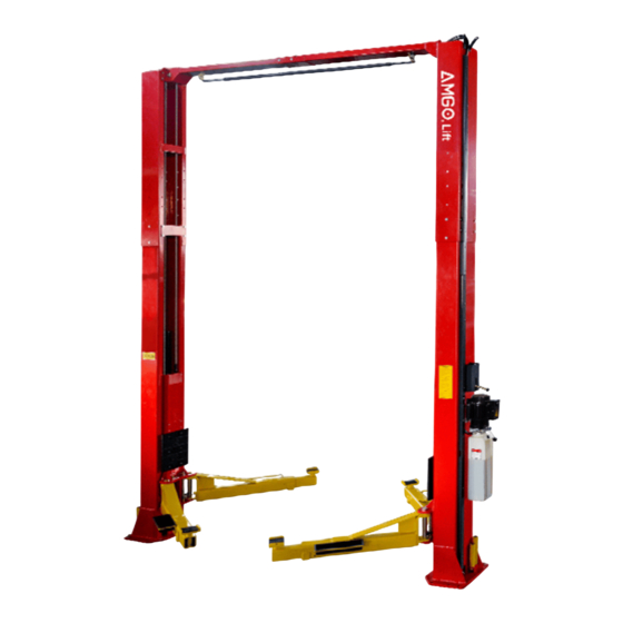
DIRECT-DRIVE TWO POST LIFT
Cargo Claims
If there is any missing or damaged
product during transportation, the
buyer must notate on the shipping
paperwork or refuse the shipment.
NOTATE ALL DAMAGE OR REFUSE
DAMAGED SHIPMENT!
Model: OH-18
△
DANGER
!
Read the entire contents of this manual before
using this product. Failure to follow instructions
and safety precautions could result in serious
injury or even death. Make sure all other
operators also read this manual. Keep this
manual near the machine so that it can be seen
by all users. By proceeding with installation and
operation, you agree that you are fully
understand the contents of this manual and take
full responsibility for the use of the product.
Advertisement
Table of Contents

Related Manuals for AMGO OH-18


Summary of Contents for AMGO OH-18
- Page 1 DIRECT-DRIVE TWO POST LIFT Model: OH-18 △ DANGER Read the entire contents of this manual before using this product. Failure to follow instructions and safety precautions could result in serious Cargo Claims injury or even death. Make sure all other If there is any missing or damaged operators also read this manual.
-
Page 2: Table Of Contents
CONTENTS PROFILE ..................1 IMPORTANT SAFETY INSTRUCTIONS ..........3 I. PRODUCT FEATURES AND SPECIFICATIONS ........5 II. INSTALLATION REQUIREMENT ............. 7 III. INSTALLATION STEPS ............... 9 IV. EXPLODED VIEW ..............33 V. TEST RUN ................40 VI. OPERATION INSTRUCTIONS ............. 41 VII. MAINTENANCE SCHEDULE ............42 VIII. -
Page 3: Profile
PROFILE The two post lift is a commonly used vehicle repair and maintenance tool that uses a pneumatic hydraulic or electric system that can lift the car up to a certain height so that the vehicle can be placed in a suitable position for inspection and repair. Car lifts can be divided into pneumatic and electric, which have the characteristics of safe and reliable, simple structure and quick installation. - Page 4 SAFETY WARNING LABEL Fig.1 Fig. 1...
-
Page 5: Important Safety Instructions
IMPORTANT SAFETY INSTRUCTIONS In order to properly maintain your product and ensure operator safety, it is the responsibility of the product owner to read and follow these instructions! 1. Ensure product installation complies with all applicable local regulations and rules, such as Occupational Safety and Health Administration regulations and electrical codes. - Page 6 clean, dry, and free of oil. 17. Stay alert. Use common sense to observe what you are doing and stay alert. 18. Check for damaged parts. Check for adjustments to moving parts, damage to parts, or anything that may affect their operation. Do not use the machine if the parts are damaged. 19.
-
Page 7: Product Features And Specifications
· Self- lubricating UHMW Polyethylene sliders and bronze bush; · Single-point safety release with dual safety design; . Clear-floor design, provide unobstructed floor use; . Overhead safety shut-off device prevents vehicle damage; MODEL OH-18 SPECIFICATION With rubber pad assy. With saddle adapter assy. Max Lifting Height... - Page 8 Arm Swings View Fig. 3 Car in Fig. 4 △ CAUTION When driving the vehicle, stay in the middle between the columns. If you hit any part of the lift, you could damage the car or lift.
-
Page 9: Installation Requirement
II. INSTALLATION REQUIREMENT TOOLS REQUIRED Rotary Hammer Drill (Φ19) Carpenter’s Chalk Hammer Screw Sets Level Bar Tape Measure (7.5m) English Spanner (12") Pliers Lock Wrench Wrench set # # # # # :(10 、13 、14... - Page 10 B. Equipment storage and installation requirements. 1.Store the equipment in a dry, non-moldy, non-flammable environment. 2.The lift is only approved for indoor installation and use, and outdoor installation is prohibited. 3.When installing the device, take safety precautions according to the instructions to avoid device damage.
-
Page 11: Installation Steps
Concrete intensity must be 3,500psi (245kg/cm²) Fig. 7 E. POWER SUPPLY 1. You are required to use a licensed and qualified electrician for the installation process. 2. The power supply require 3.0HP, with a cord larger than 12AWG, and must be properly grounded. - Page 12 Installation ceiling height requirement: larger than 14.5ft 118 1/8” 59” 3000mm (1500mm) 59” (1500mm) Car-in direction Fig. 8 △ CAUTION Installing the lift on a surface with slopes more than 3° could lead to injury or even death. This lift is designed for installation on a flat and level surface only. (Defined as no more than 3/8”...
- Page 13 Use a carpenter’s chalk line to establish installation layout of baseplate (See Fig. 9) Chalk a line 150 3/4” 3829mm Fig. 9 C. Check the parts before assembly. 1. Whole set of one unit (Packaged lift and hydraulic power unit). (See Fig. 10) Fig.
- Page 14 3. Take out top beam, then move them aside to the installation position. (See Fig. 12) Fig. 12 4. Lift the upper column with a fork lift or hoist, loose the upper bolts of the package bracket, then take out the parts inside the column. (See Fig. 13) Fig.
- Page 15 6. Move aside the parts and check the parts according to the parts list. (See Fig. 15 & 16) Fig. 16 Parts of 102 Fig. 15 7. Check the parts of the parts bag 1 and 2 according to parts bag list (See Fig. 17). Parts bag (1) Parts bag (2) Fig.
- Page 16 D. Install parts of outer columns. (See Fig. 18) Hex bolt (M6*20), flat washer, lock washer, hex nut Fig. 18 E. Confirm the installation location and install hydraulic cylinder The two columns are placed upside down on the ground of the installation site, and the installation position of the power-side column is determined according to the condition of the installation site.
- Page 17 F. Install outer columns The lift is designed with three height settings, choose high setting, medium setting or low setting in your workshop. The high setting is suitable for workshops with a height over 16.5ft; The medium setting is suitable for workshops with a height between 15.5-16.5ft; The low setting is suitable for workshops with a height between 14.5-15.5ft;...
- Page 18 G. Install anchor bolts. Position the columns on the installation layout. Check the columns plumbness with level bar, and adjusting with the shims if the columns are not vertical. Do not tighten the anchor bolts yet. (See Fig.23) Width between columns:123 1/2”...
- Page 19 H. Install overhead top beam 1. Hang the hook of top beam(with limit switch) on the power side outer column, then align the holes and install the bolts. (See Fig. 24) Install the top beam(with limit switch) to the power side column Hook on the outer columns Hex bolt(M12*35)
- Page 20 2. Hang the hook of top beam (without limit switch) on the other outer column, and then bolted to top beam . (See Fig. 25) Hex bolt(M12*35) with dual flat washer, lock washer, hex nut Tighten the anchor bolts with ratchet spanner with socket Torque of tighten the anchor bolts is 150 N.m(1328lbf.in)
- Page 21 I. Install control bar (See Fig. 26) Fix the the control bar to the control bar support brackets. Off-side Power-side Loosen the bolt slightly, adjust the distance between the two control bar support bracket till the control bar can rolls smoothly, then tighten the bolts. Control bar support bracket Hex Bolt...
- Page 22 J. Install safety lock handle (See Fig. 27). Install safety lock handle to power side safety device. Fig. 27 K. Install sync cables Raise both sides of carriages and lock them to the same level. 1. Sync cable connection of high setting installation 1.1 Remove the carriages plastic cover, sync cable across from the bottom of the carriages and pull it out from the hole of carriage, then tighten two cable nuts.
- Page 23 1.2 Connecting sync cable for high setting. (See Fig. 29) High Setting: Align lower holes of outer columns with inner columns. Cable 2 Cable 1 Cable 1 Fig. 29...
- Page 24 2. Sync cable connection of medium setting installation. (See Fig.30) Medium Setting: Align middle holes of outer columns with inner columns. Cable 2 Cable 1 Cable 2 Cable 1 Fig. 30...
- Page 25 3. Sync cable connection of low setting installation. (See Fig. 31) Attention: the sync cable should be along inside of column. Low Setting: Align upper holes of outer columns with inner columns Cable 2 Cable 1 Cable 2 Fig. 31...
- Page 26 L. Install power unit (See Fig. 32) Fig.32...
- Page 27 Install oil hose of high, medium and low setting. 1. Oil hose installation of high setting.(Fig.33) Oil hose and wire across the Oil hose across the wire support plate clamp on top beam Connect power unit fitting and oil hose Connect oil hose and cylinder Fig.33...
- Page 28 2. Oil hose installation of medium setting.(Fig.34) Fig.34 3. Oil hose installation of low setting.(Fig.35) Fig.35...
- Page 29 N. Install wire protective cover and sync cable limit plate.(See Fig.36) (No.:87 wire protective cover: not required in low setting; install 1pc for each column in medium setting; install 2pcs for each column in high setting) Socket bolt(M6*16) with flat washer, lock washer After installation of the cable, it is recommended to install...
- Page 30 O. Install lock release cable Install lock release cable. Start from off-side safety device, then pass it through the top beam, finally connect to power-side safety device. (See Fig. 37) Safety cable across outside of Safety cable wire clamp goes through small pulley bracket limit switch...
- Page 31 P. Install safety device cover (See Fig. 38) Round head bolt(M6*8), flat washer Fig.38...
- Page 32 Q. Install lifting arms 1. Install lifting arms according to the figure, then install spring on the arm pin, last install guard bar.(See Fig.39) Install with hex bolt(M8*16), lock washer, flat washer Use rubber pad or saddle adapter accordingly Fig.39 2.
- Page 33 △ WARNING Each arm restraint assembly must be inspected and adjusted before you use the Lift each and every time. Do not operate the Lift if any of the four arm restraint systems are not functioning properly. Replace any broken components or components with broken teeth with authorized replacement parts only.
- Page 34 Motor wiring diagram of single phase power unit Circuit diagram Limit switch Control button Fig. 44 Power source wires Remove this jumper wire Limit switch wire Fig. 45 Fig. 46 △ DANGER All wiring must be performed by a licensed, certified Electrician. Do not perform any maintenance or installation of the lift without first ensuring that the main power supply has been disconnected from the lift and that it cannot be re-energized until all procedures have been completed.
-
Page 35: Exploded View
IV. EXPLODED VIEW Model OH-18 Fig. 47... - Page 36 PARTS LIST FOR MODEL OH-18 Item Part# Description 1102791001A Power-side column 81513104 Power unit (071102) Hex bolt M8*25 (Include flat washer, lock washer, 1002735003 hex nut) 11217405 Power-side safety device cover 1002735004 Round head bolt M6*8 (Include flat washer) 10217005...
- Page 37 Item Part# Description 11217024 Oil hose supporter 1102791003A Outer column L=72 11/16" 11217068 Column Reinforce Plate 11217406 Offside safety device cover 10217008 Safety Spring φ2.5*145° 11217031 Offside Cam Lock 10217032 Cable connecting pin 10217033 Nylok Nut 11217029 Pulley bracket 1002735011 Hex bolt M6*15 (Include flat washer) 1102791002A Offside column...
- Page 38 Item Part# Description 11217037 Bottom pin 1102791007 Bottom pulley 5 29/32"×25/32" 10217114A Rubber pad assy. 1021103 Saddle adapter assy. 1002735012 Hex bolt M8*16/(Include flat washer, lock washer) 11206154 Rear toe guard 10206156 Tool tray 11203778-01 Wire Protective cover L=61 13/32" 1102791005 Wire Protective cover L=32 1/16"...
- Page 39 1102794001C 4.1 Lifting Arm Exploded View ( Fig. 48 Item Part# Description Qty. Socket bolt (M12*48), flat washer, lock 1102205004 washer 1102794010 Moon gear 1102794001A Outer arm 10201149 Flat head screw M8*12 1102794007A Inner arm 4.2 Cylinders Exploded View (10217056B-01) Fig.
- Page 40 Item Part# Description Qty. Note 10209069 O-Ring 10209070 Bleeding Plug 10201029 Support Ring 10201030 Y-Ring 10201031 O-Ring 11217074A Piston 10217075 O-Ring Piston rod 11217089 Piston rod fitting 11217077 Dust ring 10217078 Head cap 11217079-01 O-Ring 10217080 Bore weldment 11217091-01 Seal Kit for hydraulic cylinder: YG006 4.3 Illustration of hydraulic valve for hydraulic power unit (See Fig.
-
Page 41: Test Run
V. TEST RUN 1. Adjustment of sync cable (See Fig. 51) Use an open spanner to clamp the cable joint, and use a ratchet wrench to tighten the cable nut until the two sync cables are adjusted to a certain tension force and are consistent. - Page 42 4. Adjust the lowering speed If necessary, you can adjust the lower speed of the lift by turning the throttle valve clockwise to decrease it, or counterclockwise to increase the lower speed. Throttle Valve Throttle Valve Counterclockwise to increase lowering speed Clockwise to decrease the lowering speed Fig.
-
Page 43: Operation Instructions
5. Move the vehicle between columns; 6. Move the lifting arms to the vehicle’s lifting point; ATTENTION: Use the carrier adapter provided by the AMGO manufacturer. Swing the lifting arms under the vehicle, lift the vehicle lifting points as recommend by the vehicle manufacturer. -
Page 44: Maintenance Schedule
VII. MAINTENANCE SCHEDULE Monthly: 1. Tighten the anchor bolts with to 150 Nm torque force; 2. Check all fittings, bolts and pins to ensure proper connections; 3. Lubricate cable and slider with lubricant; 4. Make a visual inspection of all oil hoses/lines for possible wear or leakage; 5. -
Page 45: Trouble Shooting
VIII. TROUBLE SHOOTING TROUBLE CAUSE REMEDY 1. Button does not work 1. Replace button 2. Wiring connections are not in good 2.Repair all wiring connections condition Motor does not 3. Motor burned out 3. Repair or replace motor 4. Height limit switch is damaged 4.Replace the limit switch 5. -
Page 46: Car Lift Safety Tips
IX. CAR LIFT SAFETY TIPS Put these safety tips in a place where you can always alert the operator. Please reference to the lift manufacturer’s manual for specific information about the lift. 1. Check the lift daily. If the machine breaks down or has damaged parts, do not operate, and use the parts of original equipment to repair. - Page 47 72201201 2024/04...
Need help?
Do you have a question about the OH-18 and is the answer not in the manual?
Questions and answers