
Related Manuals for MAHA Twin F 3.0 A


Summary of Contents for MAHA Twin F 3.0 A
- Page 1 Twin Scissors Lift Twin F 3.0 A/U for vehicles up to 3,000 kg gross weight Operating Manual English D1 5014BA1-GB01...
- Page 2 The contents of this edition have been checked with great care. However, errors cannot be fully excluded. Please contact MAHA should you find errors of any kind. These instructions are intended for users with previous knowledge in the field of automotive vehicle service lifts.
- Page 3 PRINTING CHARACTERS AND SYMBOLS Throughout this manual, the following symbols and printing characters are used to facilitate reading: Indicates the operations which need proper care Indicates prohibition Indicates a possibility of danger for the operators Indicates the direction of access for motor vehicles to the lift BOLD TYPE Important information WARNING: before operating the lift and carrying out any adjustment, read carefully chapter 7 “installation”...
-
Page 4: Table Of Contents
CONTENTS GENERAL INFORMATION PRODUCT IDENTIFICATION PACKING, TRANSPORT AND STORAGE PRODUCT DESCRIPTION TECHNICAL SPECIFICATION SAFETY INSTALLATION OPERATION AND USE MAINTENANCE TROUBLESHOOTING 4 / 42 D1 5014BA1-GB01... -
Page 5: General Information
1 CHAPTER 1 – GENERAL INFORMATION This chapter contains warning instructions to operate the lift properly and prevent injury to operators or objects. This manual has been written to be used by shop technicians in charge of the lift (operator) and routine maintenance technician (maintenance operator). - Page 6 Before operating the lift, operators must be familiar with the position and function of all controls, as well as with the machine features shown in the chapter “Operation and use” WARNINGS Unauthorised changes and/or modifications to the machine relieve the manufacturer of any liability for possible damages to objects or people.
-
Page 7: Product Identification
2 CHAPTER 2 – PRODUCT IDENTIFICATION The identification data of the machine are shown in the label placed on the frame and indicated in the declaration of conformity. LOGO Type: ………. Model: ………. Serial Number: ………. Year of manufacturing: ………. Capacity: ………. -
Page 8: Packing, Transport And Storage
3 CHAPTER 3 - PACKING, TRANSPORT AND STORAGE Only skilled personnel who are familiar with the lift and this manual shall be allowed to carry out packing, lifting, handling, transport and unpacking operations. PACKING The lift is delivered in many components that appears sub-assembled. The lay-out is referred to the model. - Page 9 Hoist and handle only one package at a time STORAGE AND STACKING OF PACKAGES Packages must be stored in a covered place, out of direct sunlight and in low humidity, at a temperature between -10°C and +40°C. Stacking is not recommended: the package’s narrow base, as well as its considerable weight and size make it difficult and hazardous.
-
Page 10: Product Description
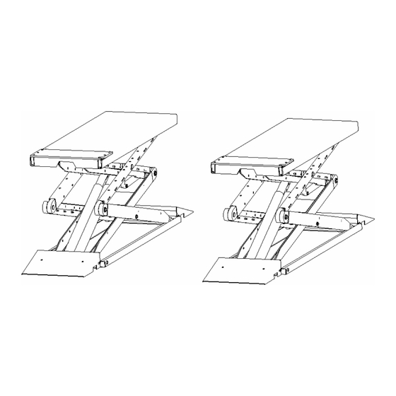
4 CHAPTER 4 - PRODUCT DESCRIPTION LIFT (Rif. Figure 2) The lift has been designed to lift motor-vehicles and make them stand at any level between the minimum and maximum height.. The maximum lifting weight, including any additional load on the vehicle, is as specified on the serial plate All mechanical frames, such as platforms, extensions, base frames and arms have been built in steel plate to make the frame stiff and strong while keeping a low weight... - Page 11 Figure 2 - LIFT 11 / 42 D1 5014BA1-GB01...
- Page 12 CONTROL DESK The Control desk is composed of: frame control panel electric motor hand pump hydraulic group oil tank leveling cock P1 Hydraulic flow divider leveling cock P2 Fig. 3 12 / 42 D1 5014BA1-GB01...
- Page 13 OPERATION Platform lifting is carried out by the hydraulic unit which acts upon the primary cylinders Lowering, even though electrically controlled, is carried out by the weight of both the platforms and the load lifted The hydraulic system is protected by a max pressure control valve thus preventing pressure from exceeding the maximum fixed safety limit Lifting and lowering motion of the lift is controlled by the push buttons on the control desk panel Whenever the lift has to be lowered to the ground and the DOWN button is pressed, the lift will...
-
Page 14: Technical Specification
5 CHAPTER 5 - TECHNICAL SPECIFICATION SIZE AND MAIN FEATURES (Rif. Figure 4) Capacity 3000 Kgp ( 29400N) Maximum lifting capacity 1900 mm Minimum height of lift 110 mm Length of the lift 1530 mm Width of the lift 1900 mm Width of platforms 525 mm Free width between platforms... - Page 15 Figure 4 – LAYOUT 15 / 42 D1 5014BA1-GB01...
- Page 16 HYDRAULIC UNIT Hydraulic group installed inside teh control unit is made of : main block hand pump lowering soleoid valve check valve max pressare valve Figure 5 - HYDRAULIC GROUP Use wear proof oil for hydraulic drive, in conformity with ISO 6743/4 rules (HM class). Fina HYDRAN TS 32 or equivalent oil with features similar to those shown in the table is recommended: EST STANDARDS EATURES...
- Page 17 CIS 32 HLP 32 CASTROL HYSPIN HWS 32 ELFONA DS 32 ESSO NUTO H 32 FIAT HTF 32 FINA HYDRAN TS 32 HYDRUS 32 HAYDYN 32 ROL OIL LI 32 SHELL TELLUS OIL 32 TOTAL AZOLLA ZS 32 HANGE HYDRAULIC OIL AT YEAR INTERVALS 17 / 42 D1 5014BA1-GB01...
- Page 18 Figure 6 - HYDRAULIC PLAN 18 / 42 D1 5014BA1-GB01...
- Page 19 Hydraulic cylinder platform P1 Check valve Hydraulic cylinder platform P2 Lowering solenoid valve Safety solenoid valve platform P1 Max pressure valve Safety solenoid valve platform P1 Pump Pressure switch Motor Pressure switch Lowering control Flow divider Filter Leveling cock P1 Tank Leveling cock P2 Hand pump...
- Page 20 Figure 7a – ELECTRIC DIAGRAM 20 / 42 D1 5014BA1-GB01...
- Page 21 Figure 7b – ELECTRIC DIAGRAM 21 / 42 D1 5014BA1-GB01...
- Page 22 Main switch Pilot lamp Fuse (20 A) Beeper Transformer fuse 0,5 A Pressure switch Auxiliary fuse 4 A Lowering solenoid valve Motor contacts EV 2 Safety solenoid valve P1 M-3 Motor EV 3 Safety solenoid valve P1 Transformer Relay – not used UP button Relay elect.
-
Page 23: Safety
6 CHAPTER 6 - SAFETY Read this chapter carefully and completely because it contains important information for the safety of the operator and the person in charge of maintenance the lift has been designed and built for lifting vehicles and making them stand above level in a closed area. - Page 24 GENERAL WARNINGS The operator and the person in charge of maintenance must follow accident-prevention laws and rules in force in the country where the lift is installed They also must carry out the following: • neither remove nor disconnect hydraulic, electric or other safety devices; •...
- Page 25 RISK OF THE VEHICLE FALLING FROM THE LIFT Vehicle falling from the lift can be caused when the vehicle is improperly placed on platforms, and when its dimensions are incompatible with the lift or by excessive movement of the vehicle. In this case, keep immediately away from the working area.
- Page 26 The presence of unauthorized persons next to the lift and on the platforms is strictly forbidden during lifting as well as when the vehicle has been already lifted Fig. 14 Any use of the lift other than that herein specified can cause serious accidents to people in close proximity of the machine.
-
Page 27: Installation
7 CHAPTER 7 - INSTALLATION Only skilled technicians, appointed by the manufacturer, or by authorized dealers, must be allowed to carry out installation. serious damage to people and to the lift can be caused if installations are made by unskilled personnel. Before carrying out any operations, remember to insert the safety piece of wood between the lower booms and the base frame (R . - Page 28 suitable for bearing maximum stress values, also in unfavorable working conditions. If in- ground/recessed installation is made, the finished size of the hole must be verified (as per drawing sent at the time of order). For installations on raised surface, compliance with the maximum carrying capacity of the surface is recommended..
- Page 29 Figure 16 – HYDRAULIC CONNECTION 29 / 42 D1 5014BA1-GB01...
- Page 30 Detail 2 Detail 1 30 / 42 D1 5014BA1-GB01...
- Page 31 STARTING • Be sure the working area is free from people and objects; • Be sure the electrical system feeding voltage is equal to that of the control box supplied with the lift (230 V OR 400 V); • Verify that the control desk is powered; •...
- Page 32 Fig. 17 Fig. 18 Fig. 19 32 / 42 D1 5014BA1-GB01...
- Page 33 7.7 PRESSURE SWITCH ADJUSTMENT If, during the installation the platforms do not lower, pressure switches could not be settled properly. To check if the pressure switches need to be regulated please proceed as follow: • Push, and keep pushing, the DOWN button (part. 5 – fig. 22) if led L5 will switch on and the lift will not lower, it means the pressure switches are not working.
- Page 34 CHECKS AND INSPECTIONS 7.8.1 MECHANICAL CHECKS • grease sliding seats of blocks placed under platforms and on bases; • lift fixing to the ground with 8 anchor bolts (min. recommended size ø = 16 mm) • bolts, connectors and connections tightened •...
- Page 35 7.10 LIMIT SWITCHES ADJUSTMENTS Only skilled personnel must be allowed to carry out this operation. An improper adjustment of limit switches could cause damages to the lift, objects and people Limit switches are adjusted by the factory. In case of improper functioning, adjust in the following way: 7.10.1 ADJUSTMENT OF MAXIMUM WORKING HEIGHT LIMIT SWITCH (FIG.
-
Page 36: Operation And Use
8 CHAPTER 8 - OPERATION AND USE CONTROLS Controls for operating the lift are: MAIN SWITCH The function control can be set in five positions: " 0 position: lift electric circuit is not powered; the switch can be padlocked to prevent the use of the lift. "... - Page 37 Lift operation can be summarized into four steps: VEHICLE POSITIONING • Place the vehicle at the centre of the platform and adjust the telescopic extensions. • Place pads under the positions indicated by the motor vehicle’s manufacturer for lifting. LIFTING •...
- Page 38 MANUAL AND EMERGENCY LOWERING If there is no power or the control box is damaged, lower the lift manually to its initial position as follows: • Disconnect main power by turning main switch on OFF ( Fig. 22 –pos.1) • Remove ring nuts (Fig. 23a -pos. 3 ) from safety valves ( 1-2 fig. 23 a) which are installed on flow divider •...
-
Page 39: Maintenance
9 CHAPTER 9 - MAINTENANCE Only trained personnel who knows how the lift works, must be allowed to service the lift. To service properly the lift, the following has to be carried out: • use only genuine spare parts as well as equipment suitable for the work required; •... - Page 40 skilled electricians 40 / 42 D1 5014BA1-GB01...
-
Page 41: Troubleshooting
10 CHAPTER 10 - TROUBLESHOOTING A list of possible troubles and solutions is given below ROUBLE OSSIBLE AUSE OLUTION The lift does not work The main switch is not turned Turn the switch on There is no power Check Power on to restore if necessary The electrical wires are Replace... - Page 42 Leakage in the hydraulic Check connections for proper pipelines. tightening and tubes for damage (replace if damaged). At least two hydraulic Check and replace if needed cylinders are faulty The lift does not lower Presence of air in the hydraulic Bleed the hydraulic system smoothly system...
Need help?
Do you have a question about the Twin F 3.0 A and is the answer not in the manual?
Questions and answers