Advertisement
Quick Links
Advertisement

Related Manuals for MAHA ECON III 5.0


Summary of Contents for MAHA ECON III 5.0
- Page 1 ECON III 5.0 Two Post Lift Technical Handbook TH362701-en...
- Page 2 The contents of this edition have been checked with great care. However, errors cannot be fully excluded. Subject to technical change without notice. OCUMENT Document №: TH362701-en Approval Date: 14.11.2008 ANUFACTURER MAHA Maschinenbau Haldenwang GmbH & Co. KG. Hoyen 20 87490 Haldenwang Germany Phone: +49 (0) 8374 585 0 Fax: +49 (0) 8374 585 499...
- Page 3 ONTENTS Specifications ......................5 Installation .........................8 Standard Delivery...........................8 Installation Checklist ........................8 Location............................8 Foundation Thickness ........................9 Positioning the Columns ........................9 Shimming the Baseplates ......................10 Aligning the Columns ........................11 Anchoring the Columns........................12 2.8.1 Anchor Installation ......................12 2.8.2 Anchor Dimensions.......................13 2.8.3 Curing Time ........................13 Electrical Connection ........................14 2.9.1 Overhead Cable Installation ..................14...
- Page 4 Motor Plate ...........................37 Support Bearings for Lifting Screw ....................38 3.5.1 Upper Bearing.......................38 3.5.2 Lower Bearing.......................39 Drive Motor...........................40 Manual Lowering..........................41 Aligning the Pulleys........................42 Maintenance Schedule.........................42 3.9.1 Checking the Load Nut for Wear ..................43 3.9.2 Greasing the Load Nut....................44 3.9.3 Greasing the Slide Tracks ....................45 3.9.4 Greasing the Arm Extensions..................46 3.9.5...
- Page 5 This Technical Handbook is to be used exclusively by trained service personnel. Regulations and guidelines in the Operating Manual listed under section "Safety" apply in all cases! Specifications See following pages. TH362701-en...
- Page 6 TH362701-en...
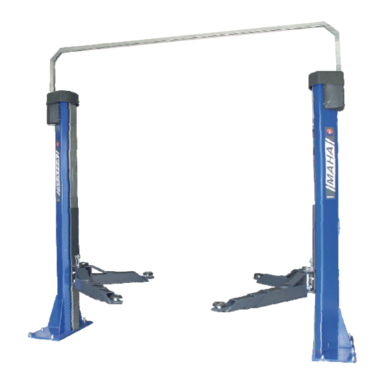
- Page 7 ECON III 5.0 Overall height HG 5043 mm Clearance height HL 5002 mm Column height HS 3138 mm Full travel HW 1885 mm Lifting height max. HO 2025 mm Lifting height min. HU 140 mm Disk adjustment range HT 110…140 mm Support arm reach LT 914…2000 mm...
- Page 8 Installation Lift installation and commissioning only by manufacturer authorized service personnel. Standard Delivery • 2 columns with 1 control unit • 4 support arms, double telescopic • Overhead cable guide (with overhead cable installation) or extended connecting cables (with inground cable installation) •...
- Page 9 Foundation Thickness Proof of safe floor load capacity is the owner's responsibility. Always use the current foundation plans. Foundation thickness 220 mm Positioning the Columns For details and dimensions see applicable data sheet. TH362701-en...
- Page 10 1 Transport the lift to its final location and remove the packaging material. 2 Position the columns using the dimensions indicated in the applicable data sheet. Place the operating column (1) on the right side as seen from approach direction (2). The clearance between the columns can be determined e.g.
- Page 11 Aligning the Columns Inside columns BL 3023 mm 1 Align the columns in a slightly V-shaped position (see also section "Shimming the Base- plates"). The clearance between the upper column ends should be 15 mm larger than the clearance between the lower column ends. 2 Check the alignment using a contractor's level.
- Page 12 Anchoring the Columns 2.8.1 Anchor Installation Pos: 4 /Technische Dokumentation/MAHA/HBZ/Alle HBZ/TH/Inhalte/Inhalt: Info - Anleitung und Website MKT @ 10\mod_1222947744495_75.doc @ 248516 Detailed installation instructions come with the product. For further information go to the anchor manufacturer's website: http://www.mkt-duebel.de/mkt-home_eng.htm Pos: 5 /Technische Dokumentation/MAHA/HBZ/Alle HBZ/TH/Inhalte/Inhalt: Ankermontage (Bilder) MKT-VMZ @ 10\mod_1222932508527_0.doc @ 248220 Pos: 6 /Technische Dokumentation/MAHA/HBZ/Alle HBZ/TH/Inhalte/Inhalt: Ankermontage+Art.Nr.
- Page 13 Pos: 7 /Technische Dokumentation/MAHA/HBZ/Alle HBZ/TH/Überschriften/Überschrift 1.1.1: Ankermaße @ 8\mod_1206627501012_75.doc @ 178828 2.8.2 Anchor Dimensions Pos: 8 /Technische Dokumentation/MAHA/HBZ/Alle HBZ/TH/Inhalte/Inhalt: Ankermaße (Tabelle) MKT-VMZ @ 10\mod_1222937251011_75.doc @ 248412 VMZ-A 100 M12 145 M16 170 M20 Drill hole diameter [mm] Diameter of clearance hole in...
- Page 14 Electrical Connection Remove the mains fuse before installing or servicing the electrical equipment. Do not carry out any changes on the prewired control system. 2.9.1 Overhead Cable Installation Run the power supply cords and air hoses through the channels provided inside the columns.
- Page 15 2.11 Installing the Controller Board Sensitive electronic components! Risk of damage! The controller board may be damaged or destroyed by electrostatic diskharge. Before installing the controller board assembly touch a grounded metal object. During installation hold the controller board on the edge and avoid contact with any components.
- Page 16 2.12 Installing Strain Relief Clips 1 The strain relief clips at the cable exit from the column (A) and at the motor (B) are preinstalled at the factory. Check if they are present and complete them if necessary. 2 After connecting the cables install a strain relief clip (C) beneath the controller board.
- Page 17 2.13 Connector Pin Assignment and Contactors X1 Mains Connector Description Remarks X1.1 X1.2 X1.3 X1.4 X1.5 X2 Namur Switches, Operating Column Description Remarks X2.1 Lower Namur Switch – (Limit Switch) Blue X2.2 Lower Namur Switch + (Limit Switch) Brown X3 Namur Switches, Operating Column (X3 marked with white dot on controller board) Description Remarks X3.1...
- Page 18 X5 Serial Interface Description Remarks X5.1 +5 V X5.2 TTL Level X5.3 TTL Level X5.4 X6 Motor Connector, Operating Column Description Remarks X6.1 X6.2 X6.3 X6.4 X7 Motor Connector, Second Column Description Remarks X7.1 X7.2 X7.3 X7.4 X8 Ceiling Light Barrier Description Remarks X8.1...
- Page 19 Fuse (time delay) Rated current in kW in A in A ECON III 5.0 2 x 3.5 The wire size must be selected depending on lift model and cord length. Wire designation / Wire color Terminal of control unit of power supply cord...
- Page 20 2.15 Installing the Cable Guide and the Motor Covers 1 Bend the vertical cable channels in such a way that the connecting links are on top. 2 Fasten the links using two self-tapping screws. 3 Install the cable channels to the columns (2x M6 oder M8). Fold the link (A) at the bottom end of the cable channel to the inside so that it rests on the stop pin (B).
- Page 21 2.16 Installing the Support Arms 1 Pre-install the gears using four fastening screws M10 (A) on each support arm. Do not tighten screws yet. 2 Insert the support arms into the carriages and fasten them using the arm pins. 3 Secure the arm pins at the top and the bottom using snap rings (B).
- Page 22 2.18 Installing the Door Protection Strips • Install the sponge rubber strips on the inner edges of the support arm gussets. Position the door protection strips as required by the vehicle type to be lifted. 2.19 Initial Operation During initial operation the pulse generators will not be monitored. This means the following functions are disabled: •...
- Page 23 1 Push and hold the LOWER button for 10 seconds. ⇒ Lift lowers. Risk of damage! If lift raises, release button immediately. To rectify the phase sequence two phases must be interchanged. 2 Lower lift to bottom position. ⇒ All LEDs light up. Lift is ready for operation.
- Page 24 2.19.4 Namur LEDs on Controller Board Display Description Remarks LEDs are positioned according Namur LED flashes cycli- Interruption of Namur switch. to the corresponding Namur cally 3x and extinguishes. switch connections. LEDs are positioned according Namur LED flashes cycli- Short circuit of Namur switch. to the corresponding Namur cally 3x and lights.
- Page 25 Service Information Controller Board 3.1.1 LED Display Unit LEDs VD1 (red) , VD2 (yellow) and VD3 (green) indicate operating states and errors. 3.1.2 Connector Pin Assignment See section "Installation / Connector Pin Assignment and Contactors". 3.1.3 Connector Types Connector Circuit Card Number of Poles Type of Contact Type of Opposite Connector...
- Page 26 3.1.5 Serial Interface Interface with 5 V level, adapter required. Interface Settings Baud rate....38400 Baud Data bits ....8 Stop bit ....1 Parity ....none ECON Manager (KE Tool) Settings In menu <Options / Set File Paths and Names> make the settings for the MOT file (software update for control unit), and for the EEPROM texts.txt.
- Page 27 3.1.6 EEPROM Variables № Description Default Not blank Pattern – Do not change! EEPROM version Position 1 [Digit] Position 2 [Digit] Check sum of positions (XOR) Maximum lifting height [Digit] 2236 Pinch point position [Digit] Control On-threshold [Digit] Control Off-threshold [Digit] 10 Maximum difference [Digit]...
- Page 28 № Description Default 32 Flag for power failure during lowering [0/1] 35 Load nut failure counter 1 36 Load nut failure counter 2 37 Sluggish operation counter Up 1 38 Sluggish operation counter Up 2 39 Obstruction counter Down 1 40 Obstruction counter Down 2 41 Floor contact counter 1 42 Floor contact counter 2...
- Page 29 Behavior of Lift Control System 3.2.1 Emergency-Down (previously "Trial Run") During the emergency-down watch both carriages and the vehicle contiuously. If the vehicle is in danger of getting off balance, stop the lift immediately. During the emergency-down the pulse generators will not be monitored. This means the following functions are disabled: •...
- Page 30 Yellow LED not flashing • If the yellow LED is not flashing, push and hold the LOWER and RAISE buttons simultaneously for 10 seconds. Then proceed as explained under section "Yellow LED flashing". 3.2.3 Load Nut Failure Load nut failure is stored in the control system by setting the "load nut failure flag" and is indicated by the red LED lighting up and the yellow LED flashing at the same time.
- Page 31 1 Raise or lower the lift until the inspection windows in the carriages line up with the windows in the screw drive covers. 2 Check the clearance between load nut (1) and safety nut (2). With an undamaged load nut, the clearance is 21…24 mm. With a broken load nut, the clearance and the red paint are no longer detectable.
- Page 32 3.2.4 Floor Contact of Support Arms Floor contact of support arms is detected by the lift control if the upper pulse generators transmit too few or no pulses at a lifting height of less than 30 mm. This status is detected and stored by the lift control and indicated by the yellow LED.
- Page 33 3.2.7 Level Difference between Carriages Level differences between the carriages (≥ 26 mm) are corrected automatically by the lift control. However, if the level difference exceeds 10 cm due to an error, the lift stops, the yellow LED flashes and the control is disabled. Lower the lift either manually or by performing an emergency-down.
- Page 34 Signals during Regular Operation Indication Description Remarks Green LED lights up. Lift switched on, no errors. Audible signal while lowering, lift Lift has reached pinch point Release button, press again. stops. position. Lift is lowering and below pinch Audible signal while lowering. point position.
- Page 35 Bootloader Signals Indication Description Remarks Start application using Windows Green and red LEDs light up. Control in bootloader. tool or by voltage cutoff. Green LED lights up, red LED Bootloader performing a software Wait until red LED stops flickers. update. flickering.
- Page 36 Upper and Lower Proximity Switches 3.3.1 Adjusting the Upper Proximity Switches (Pulse Generators) The pulse generators are fastened to a holder under the motor plate by means of lock nuts. 1 Open the lock nuts (1.1). 2 Adjust the clearance between the pulse generators (1) and the teeth of the pulse generator wheel (2) to 1…1.2 mm.
- Page 37 3.3.2 Adjusting the Lower Proximity Switches (Limit Switches) • The clearance between the upper edge of the limit switch and the upper edge of the mounting bracket must be set to 10 mm. Motor Plate To install the motor plate on the column use 4 fastening bows M8-8.8 and 8 hex nuts M8-8 DIN EN ISO 10511.
- Page 38 Support Bearings for Lifting Screw 3.5.1 Upper Bearing Sensitive components! Risk of damage! Use caution when removing the flange bearing (item 8). The bearing may be easily damaged as it absorbs forces in one direction only. Hex Nut M24x2-8 Washer A25 DIN125 Ribbed Pulley (Large) Shim Ring 28x40x2 Shim Ring 30x42x2,5...
- Page 39 3.5.2 Lower Bearing Lifting Screw Hex Screw M6x20 Flange Bearing igubal EFOM Baseplate Item Description Installation torque Hex Screw M6x20 Torque to 10.5 Nm. TH362701-en...
- Page 40 Drive Motor Hex Screw M8x16-8.8 Hex Screw M8x30-8.8 Hex Nut M8-8 DIN EN ISO 10511 Hex Screw M8x35-8.8 Belt Tensioner (Long) Belt Tensioner (Short) Washer A8.4 DIN 7349 Ribbed Pulley (Small) Threaded Pin M5x8 DIN 914-45H Feather Key A8x7x50 Drive Motor Item Description Installation torque Hex Screw M8x30-8.8...
- Page 41 Manual Lowering Authorized personnel only! Do not restart the lift before the error has been remedied. In case of motor defect or power failure the carriages can be lowered manually. The lift may only be lowered, not raised. 1 Open fastening screws and remove motor covers from both columns.
- Page 42 Aligning the Pulleys Make sure the pulleys of motor and lifting screw are in alignment. Misalignment exceeding ± 0.5 mm is not permissible. The motor pulley is fastened using a setscrew. • Open the setscrew and adjust the motor pulley until it aligns with the lifting screw pulley.
- Page 43 3.9.1 Checking the Load Nut for Wear Once a year check the load nuts for wear. Shut down and lock the lift until the worn-out load nut has been replaced. 1 Raise or lower the lift until the inspection windows in the carriages line up with the windows in the screw drive covers.
- Page 44 After servicing the carriage (e.g. load nut replacement) proceed as follows: 1 Raise the lift to upper end position. 2 Briefly unscrew the motor plate, centre it, fasten it again. 3 Lower the lift to bottom position. 4 Briefly unscrew the lower support bearing, fasten it again. 5 Recheck the clearance between check screw and safety nut.
- Page 45 3.9.3 Greasing the Slide Tracks The slide tracks inside the columns should be greased every six months or more frequently if required. 1 Fully lower the lift. 2 Open fastening screws and remove motor covers from both columns. 3 Open upper fastening screws of screw drive cover and remove cover.
- Page 46 3.9.4 Greasing the Arm Extensions 1 Every six months check the support arm extensions for smooth operation. 2 Grease as required. 3.9.5 Greasing the Disk Adapter Threads 1 Every six months check the threads of the disk adapters for smooth operation. 2 Grease as required.
- Page 47 Arm Restraints 1 Periodically check the restraint pin (A) for smooth and secure engagement. 2 If required, slightly grease the contact points of the gear segments (B). Ribbed V-Belts Once a year check the ribbed V-belts for wear, soiling and correct tension. Worn-out belts have to be replaced.
- Page 48 Adjusting the Belt Tension 1 Open fastening screws and remove motor covers from both columns. Do not remove the mounting brackets of the motor covers! 2 Slightly open the fastening screws (A) of the motor. 3 Slightly open the fastening screw (B) of the tensioning device. 4 Tension the belt using the tensioning screw and nut (C).
- Page 49 3.9.7 Checking the Lift Stability 1 Every six months check the nuts of all anchor bolts for correct installation torque using a torque wrench. inst 2 Retighten the nuts as required. Installation torque T 80 Nm inst TH362701-en...
Need help?
Do you have a question about the ECON III 5.0 and is the answer not in the manual?
Questions and answers