Sign In
Upload
Download
Table of Contents
Contents
Add to my manuals
Delete from my manuals
Share
URL of this page:
HTML Link:
Bookmark this page
Add
Manual will be automatically added to "My Manuals"
Print this page
×
Bookmark added
×
Added to my manuals
Manuals
Brands
MAHA Manuals
Lifting Systems
MA STAR 3.5
Operating instructions manual
MAHA MA STAR 3.5 Operating Instructions Manual
Two post lift
Hide thumbs
1
2
Table Of Contents
3
4
5
6
7
8
9
10
11
12
13
14
15
16
17
18
19
20
21
22
page
of
22
Go
/
22
Contents
Table of Contents
Troubleshooting
Bookmarks
Table of Contents
Table of Contents
General Safety Instructions
Introduction
Symbols and Signal Words
Personal Injury
Property Damage
What to Do in the Event of Defects or Malfunctions
What to Do in the Event of an Accident
Requirements for the Operating Personnel
Requirements on Service Personnel
Intended Use
Inappropriate Use
Transport, Handling and Storage
Safety Instructions
Scope of Delivery
Packaging Information
Dimensions and Weight
Centre of Gravity of the Packaged Lift
Transport and Handling
Storage
Operation
Safety Instructions
Operation and Operating States
Preparing the Lifting Operation
Establishing Operational Readiness
Positioning the Vehicle
Positioning the Support Arms and Pick-Up Plates
Raising and Lowering Cycles
Inspecting the Load Pick-Up Points and Support Arm Locks
Lashing the Vehicle
Continuing the Lifting Process
Lowering Process
Driving the Vehicle off the Lift
Troubleshooting
Troubleshooting Table
Determining Defective Sensors
Declaration of Conformity
Advertisement
Quick Links
Download this manual
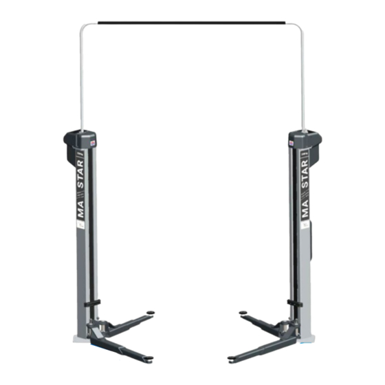
MA STAR 3.5 | 5.5 | 6.5
Two Post Lifts
Extract from the Original Operating Instructions
BA364501_101-en
Table of
Contents
Previous
Page
Next
Page
1
2
3
4
5
Advertisement
Table of Contents
Need help?
Do you have a question about the MA STAR 3.5 and is the answer not in the manual?
Ask a question
Questions and answers
Related Manuals for MAHA MA STAR 3.5
Lifting Systems MAHA MA STAR Series Original Operating Instructions
Two post lifts (36 pages)
Lifting Systems MAHA MA STAR 5.5 Original Operating Instructions
Two post lift (35 pages)
Lifting Systems MAHA MA STAR 3.5 A Operating Instructions Manual
Two post lift (30 pages)
Lifting Systems MAHA MA STAR 6.5 Operating Instructions Manual
Two post lift (22 pages)
Lifting Systems MAHA ZS SQUARE Technical Handbook
One/two post inground lifts (80 pages)
Lifting Systems MAHA MLS Series Original Operating Instructions
Weight simulators (30 pages)
Lifting Systems MAHA ECON III 3.0 Technical Handbook
Two post lift (59 pages)
Lifting Systems MAHA ECON II 3.0 Technical Handbook
Two post lift (45 pages)
Lifting Systems MAHA DUO GN Series Original Operating Instructions
(37 pages)
Lifting Systems MAHA DUO-GN Technical Handbook
Scissors lift (96 pages)
Lifting Systems MAHA ECONLIFT 6500 Original Operating Instructions
Two post lift (32 pages)
Lifting Systems MAHA MGH Series Original Operating Instructions
Pit jack (34 pages)
Lifting Systems MAHA HL CS Series Operating Instructions Manual
Two post lifts (23 pages)
Lifting Systems MAHA CARLIFT 4.1 Technical Handbook
Four post lift for vehicles up to 4,000 kg gross weight (42 pages)
Lifting Systems MAHA ZS SQUARE II 3.5 Original Operating Instructions
Two post lifts with flat head or swing arm supports (52 pages)
Lifting Systems MAHA ZS SQUARE II Series Original Operating Instructions
Two post inground lift (36 pages)
This manual is also suitable for:
Ma star 5.5
Ma star 6.5
Vp 451190
Vp 451187
Vp 251233
Table of Contents
Print
Rename the bookmark
Delete bookmark?
Delete from my manuals?
Login
Sign In
OR
Sign in with Facebook
Sign in with Google
Upload manual
Upload from disk
Upload from URL


Need help?
Do you have a question about the MA STAR 3.5 and is the answer not in the manual?
Questions and answers