Table of Contents
Advertisement
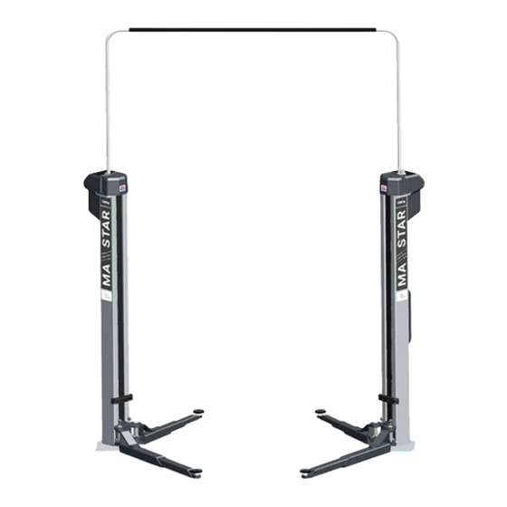
MA STAR 3.5 A/S
Two Post Lift
Original Operating Instructions
BA364501-en
Fehler! Verwenden Sie die Registerkarte 'Start', um Name dem Text zuzuweisen, der hier angezeigt werden soll.Fehler! Verwenden Sie die
Registerkarte 'Start', um Name dem Text zuzuweisen, der hier angezeigt werden soll.Fehler! Verwenden Sie die Registerkarte 'Start', um
Name dem Text zuzuweisen, der hier angezeigt werden soll.
Advertisement
Table of Contents

Related Manuals for MAHA MA STAR 3.5 A


Summary of Contents for MAHA MA STAR 3.5 A
- Page 1 MA STAR 3.5 A/S Two Post Lift Original Operating Instructions BA364501-en Fehler! Verwenden Sie die Registerkarte 'Start', um Name dem Text zuzuweisen, der hier angezeigt werden soll.Fehler! Verwenden Sie die Registerkarte 'Start', um Name dem Text zuzuweisen, der hier angezeigt werden soll.Fehler! Verwenden Sie die Registerkarte 'Start', um...
- Page 2 BA364501-en 2020-03-17 © MAHA Maschinenbau Haldenwang GmbH & Co. KG The reproduction, distribution and utilization of this document as well as the communication of its con- tents to others without explicit authorization is prohibited. Offenders will be held liable for the payment of damages.
-
Page 3: Table Of Contents
Contents General Safety Instructions ..................... 5 Introduction ........................... 5 Symbols and Signal Words ..................... 5 1.2.1 Personal Injury ........................ 5 1.2.2 Property Damage ........................ 5 1.2.3 Information .......................... 6 What to Do in the Event of Defects or Malfunctions ............ 6 What to Do in the Event of an Accident ................ 6 ... - Page 4 Operation ........................ 1 8 Safety Information ....................... 1 8 Intuitive Control and Operating States ................ 2 0 Preparations ......................... 2 1 4.3.1 Initial Position/Ready for Operation .................. 2 1 4.3.2 Positioning of the Vehicle .................... 2 1 4.3.3 Positioning of the Support Arms and Support Discs ...
-
Page 5: General Safety Instructions
General Safety Instructions Introduction These operating instructions must be read carefully and understood before work commences. Please observe the specific safety information provided for the respective sections of the operating instructions. Adhering to the procedures, sequences and corresponding safety instructions is es‐ sential. A printed copy of the operating instructions must always be kept by the lift. The relevant regulations regarding accident prevention and health and safety must be observed. Symbols and Signal Words 1.2.1 Personal Injury DANGER indicates an immediate hazard which, if not avoided, will result in death or severe per‐ sonal injury. WARNING indicates a potential hazard which, if not avoided, could result in death or severe per‐ sonal injury. CAUTION indicates a potential hazard which, if not avoided, could result in moderate or minor personal injury. 1.2.2 Property Damage ... -
Page 6: Information
1.2.3 Information indicates important information notes. What to Do in the Event of Defects or Malfunctions If a malfunction occurs, e.g. uncontrolled raising and lowering or in the case of load‐ bearing components of the structure becoming deformed, immediately lower the lift to the ground to its initial position or support the structure. Turn off the main switch and secure against unauthorised use. Contact service team. What to Do in the Event of an Accident Notify first aiders, the ambulance service and/or immediate care doctor: Where did the accident happen (address, workshop, ...)? What happened? How many are injured? What injuries have occurred? Who is reporting the accident? Keep calm and answer questions. Requirements on Operating and Service Personnel All persons involved in the operation, maintenance, installation, dismantling and disposal of the equipment must be 18 years of age or older, have the mental and physical capacity for their role, be qualified and have the documentation to verify this, have read and understood the operating instructions, and in particular the instruc‐ tions on the procedure in the event of a malfunction, have had certified training regarding safety regulations, ... -
Page 7: Description
2.3.1 Design and Basic Functions The MA STAR 3.5 A/S two post lift consists of two industrially rolled columns with welded-on base plates. The base plates ensure the columns are securely anchored to the ground. The column profile bears the weight of the lifted vehicle, accommodating the lifting carriage on the inner panel and the control unit on the outer panel. -
Page 8: Intended Use
The lift drive consists of an electric motor with an electric release brake, which moves a Tr 40x6 spindle via a belt drive. A lifting or lowering movement is thereby triggered via the anti-rotation secured nut in the lifting carriage depending on the direction of rotation. -
Page 9: Overall View With Components
2.3.3 Overall View with Components A Control column a Toothed belt drive B Opposite column b Trapezoidal spindle Cable bridge c Nut package D Control unit d Lifting carriage (with support arm brackets) Drive motor Support arms e Support arm lock G Connector plug BA364501-en... -
Page 10: Technical Data
Technical Data 2.4.1 Technical Data MA STAR 3.5 A Load capacity ......................3500 kg Short support arm rotating capacity ................180° Long support arm rotating capacity ................102.5° Raising time (depending on load) approx..............40 s Lowering time (depending on load) approx..............40 s Drive power .................. -
Page 11: Installation Diagram Ma Star 3.5
2.4.3 Installation Diagram MA STAR 3.5 A * Dimensions refer to the recommended drive-through width of 2400 mm. BA364501-en... -
Page 12: Technical Data Ma Star 3.5
2.4.4 Technical Data MA STAR 3.5 S Load capacity ......................3500 kg Support arm rotating capacity .................. 102.5° Raising time (depending on load) approx..............40 s Lowering time (depending on load) approx..............40 s Drive power ..................2 x 3.0 kW (S3-20%) Power supply .................. -
Page 13: Installation Diagram Ma Star 3.5
2.4.6 Installation Diagram MA STAR 3.5 S * Dimensions refer to the recommended drive-through width of 2400 mm. BA364501-en... -
Page 14: Control Description
Control Description The lift is operated at the control unit with two push buttons. These have arrows, which show the direction of movement. Their blue light, which activates according to operating status and possible directions of movement, enables intuitive operation of the lift. -
Page 15: Transport, Handling And Storage
Transport, Handling and Storage Safety Information WARNING Wear personal protective equipment. Standing under a suspended load is prohibited. The transport and storage of packages is only permitted using original transport racks. Observe the max. stacking height. Before removing the packaging straps, secure the packages against falling and main- tain a safe distance. -
Page 16: Packaging Information
Packaging Information 3.3.1 Packaging MA STAR 3.5 A Dimensions (L x W x H) ..............2925 x 1100 x 710 mm Weight ........................740 kg 3.3.2 Packaging MA STAR 3.5 S Dimensions (L x W x H) ..............2925 x 1100 x 710 mm Weight ........................ -
Page 17: Transport And Handling
Transport and Handling The transport and handling of the lift is only permitted using the original transport racks. The pick-up points shown below must be used for the loading and unloading of the packaged lift. IMPORTANT: Strapping of the columns is not permitted! The dimensions and centre of gravity of the packaged lift are shown in the section “Packaging Information”. -
Page 18: Operation
Operation Safety Information WARNING Observe the detailed operating instructions. Comply with legal accident prevention regulations. Wear personal protective equipment. Carry out visual and operational checks daily before the commencement of work (see also section “Test and Maintenance Schedule”). ... - Page 19 Climbing on the raised vehicle or on the lift is prohibited. There must not be any people or objects within the safety zone of the lift and the load during the raising and lowering process. Monitor the load and the lift during raising and lowering. In the event of an irregu- larity, the emergency stop button (main button on the main operating column or the emergency stop button on the second control unit on the opposite column), must be pressed immediately.
-
Page 20: Intuitive Control And Operating States
Intuitive Control and Operating States The lift has been fitted with an intuitive operating system. Depending on the operating status, illuminated buttons provide a visual indication of the lift’s available options regarding direction of movement. Lift switched off Only raising pos- Raising and low- Only lowering Fault, lift not... -
Page 21: Preparations
The main switch must be at position 0. The lift must be fully lowered. The support arms must be pivoted completely away from the working area (initial position, see diagram.) MA STAR 3.5 A MA STAR 3.5 S 4.3.2 Positioning of the Vehicle ... -
Page 22: Positioning Of The Support Arms And Support Discs
Swivel and extend the support arms to position the support discs under the pick-up points specified by the vehicle manufacturer. Turn the support discs so that all four pick-up points are accessed evenly. MA STAR 3.5 A MA STAR 3.5 S 4.3.4 Support Disc Raisers ... -
Page 23: Raising And Lowering Cycles
Raising and Lowering Cycles 4.4.1 Inspection of the Load Pick-up Points and Support Arm Locks Set the main switch to position 1. After an initial flashing of all three lights, the UP button is permanently lit. Press the UP button until the support discs are in contact with the pick-up points of the vehicle. -
Page 24: Lowering Process And Ce Stop
4.4.3 Lowering Process and CE Stop Before lowering the vehicle, remove tools, support stands or similar obstacles from the working area of the lift. The operator is responsible for ensuring that nobody is within the danger area. Press and hold the lit DOWN button until the desired lifting height is reached. ... -
Page 25: Inspection And Maintenance
Inspection and Maintenance Safety Information WARNING The relevant health and safety regulations must be observed. Wear personal protective equipment. Service work may only be carried out by authorised service technicians. Repairs, maintenance and set‐up work may only be carried out when the machinery is stationary. The unit must be disconnected from the power supply and secured against being switched on again. Work on the electrical part of the lift may only be carried out by qualified staff or specialist electricians. ATTENTION: The 230V plug sockets on the operation unit(s) still carry power even after the system has been switched off! Maintenance and repair work may only be carried out when the lift is load‐free. Only use original replacement parts. Substances that are hazardous to the environment must be disposed of appropri‐ ately. Do not use high or steam pressure equipment or harsh cleaning agents to clean the lift. The safety features of the lift must be set by authorised service technicians. The safety features must not be replaced or overridden. Inspection and Maintenance Plan Daily before operating ... - Page 26 Every 6 months Spindles and support nuts: Check fill level of oil pan in the lifting carriage, top up with SAE140 gear oil as necessary. Check slider tracks for free movement, lubricate as required. Check support arm extensions for free movement, lubricate as required. ...
-
Page 27: Care Instructions
Care Instructions Periodically clean the equipment and treat it with a care product. Repair damage to the paintwork immediately to prevent corrosion. Do not use caustic cleaning agents or high pressure and steam jet cleaners to avoid equipment damage. Regular care and maintenance is the key condition for functionality and long life expec‐ tancy of the equipment! Troubleshooting Safety Information WARNING The relevant health and safety regulations must be observed. Wear personal protective equipment. Service work may only be carried out by authorised service technicians. Repairs, maintenance and set‐up work may only be carried out when the machinery is stationary. The unit must be disconnected from the power supply and secured against being switched on again. Work on the electrical part of the lift may only be carried out by qualified staff or specialist electricians. ATTENTION: The 230V plug sockets on the operation unit(s) still carry power even after the system has been switched off! Maintenance and repair work may only be carried out when the lift is load‐free. Only use original replacement parts. Substances that are hazardous to the environment must be disposed of appropri‐ ately. ... -
Page 28: Error Chart
Error Chart Display Diagnostics Remedy Button pressed by mistake. Release button. Signal sound immediately upon switching on. Control panel has short circuit. Notify service team. Lift can only move upwards. If necessary, the lower end po- Lift has reached its end posi- sition can be adjusted to tion. -
Page 29: Repairs
Repairs See repair instructions in the lift's technical handbook. Decommissioning, Dismantling and Disposal Decommissioning and dismantling of the equipment may be done only by specially authorized and trained personnel provided by the manufacturer, licensed dealers or service partners. Pay attention to the product and safety data sheets of the lubricant used. Avoid damage to the environment. - Page 30 Original Declaration of Conformity MAHA Maschinenbau Haldenwang GmbH & Co. KG herewith declares as a manufacturer its sole responsibility to ensure that the product named hereafter meets the safety and health regulations both in design and construction required by the directives stated below. This declaration becomes void if any change is made to the product that was not discussed and approved by named company beforehand. Model VP Number MA STAR 3.5 A VP 251230 + VP 251232 MA STAR 3.5 S VP 251231 + VP 251233 Designation Two Post Lift Rated Load Capacity: 3500 kg Directives 2006/42/EC 2014/30/EU Standards DIN EN 1493:2010 DIN EN 60204‐1 DIN EN ISO 13849‐1 Person Authorised to Compile the Technical File Ralf Kerkmeier, MAHA Maschinenbau Haldenwang GmbH & Co. KG, Hoyen 20, 87490 Haldenwang, Germany Haldenwang, 2020‐03‐05 Andreas Maier Head of Mechanical Development ...
Need help?
Do you have a question about the MA STAR 3.5 A and is the answer not in the manual?
Questions and answers