
Related Manuals for MAHA ECON II 3.0


Summary of Contents for MAHA ECON II 3.0
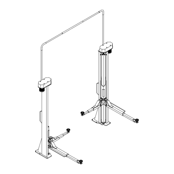
- Page 1 Two Post Lift ECON II 3.0 for vehicles up to 3,000 kg gross weight ECON II 3.5 for vehicles up to 3,500 kg gross weight Technical Handbook English D1 3619TH1-GB05...
- Page 2 The contents of this edition have been checked with great care. However, errors cannot be fully excluded. Please contact MAHA should you find errors of any kind. These instructions are intended for users with previous knowledge in the field of automotive vehicle service lifts.
-
Page 3: Table Of Contents
ECON II 3.0 / ECON II 3.5 ONTENTS Description ........................ 1 Standard Delivery .......................... 1 Options / Accessories ........................1 Noise Emission ..........................1 Specifications..........................2 Installation Requirements ......................4 1.5.1 Location .......................... 4 1.5.2 Foundation........................4 1.5.3 Power/Air Supply ......................4 Installation ......................... - Page 4 ECON II 3.0 / ECON II 3.5 3.10 Sensor Voltage ..........................32 3.11 Manual Lowering.......................... 32 3.12 Load Nut Wear Check........................33 3.13 Greasing Points ........................... 34 3.13.1 Load Nut ........................34 3.13.2 Slide Tracks........................35 3.13.3 Lifting Screw Bearing....................35 3.13.4...
-
Page 5: Description
ECON II 3.0 / ECON II 3.5 Description Standard Delivery Š 2 columns including control box Š 2 long swing arms; 2 short swing arms Š Overhead cable guide Š Operation manual Š Packaging Options / Accessories Š Additional control box for slave column Š... -
Page 6: Specifications
ECON II 3.0 / ECON II 3.5 Description Specifications D1 3619TH1-GB05... - Page 7 Description ECON II 3.0 / ECON II 3.5 ECON II 3.0 ECON II 3.5 Load capacity 3000 kg 3500 kg Raising / Lowering time 42 s (MB: 35 s) Height overall HG 4600 mm 4850 mm Floor to overhead guide HL...
-
Page 8: Installation Requirements
Foundation Prior to installation a sufficiently stable foundation and level lift bay floor shall be completed in accordance with MAHA recommendations. Minimum concrete thickness: 175 mm reinforced. Always use the latest foundation plans available through MAHA. Proof of safe floor load capacity is the owner's responsibility. -
Page 9: Installation
ECON II 3.0 / ECON II 3.5 Installation Positioning Before standing the columns upright screw the cover hood fasteners into the motor plate. (See section "Cover Hood Installation".) For details and dimensions see data sheets in section "Appendix". Š Remove the packaging material. Stand the columns upright using applicable data sheet. -
Page 10: Anchoring
ECON II 3.0 / ECON II 3.5 Installation Š Level and plumb each column using a contractor's level and shims as required. Measure at same height on all sides, e.g. at eye level. For inground wiring see applicable section in this manual. -
Page 11: Anchors
Installation ECON II 3.0 / ECON II 3.5 Use flat washers A17 DIN 7349 (Ø 40 mm, thickness 6 mm). ‹ MAHA part 22 7349 16 1 2.2.1 Anchors Min. hole depth w/o fixture, tiles Max. thickness of Min. embedment Drill bit ∅... -
Page 12: Procedure
ECON II 3.0 / ECON II 3.5 Installation 2.2.2 Procedure Anchor setting in through holes results in faulty installation. Drill a hole into the base material as per anchor manufacturer's recommendations. Blow the hole clean of dust and other material. -
Page 13: Electrical Installation
Installation ECON II 3.0 / ECON II 3.5 Electrical Installation Remove the power fuse before installing or servicing the electrical equipment. Do not change the prewired circuit board in the control unit. Run a potential equalization cable (wire size 4 mm²) from each column to the control unit. -
Page 14: Motor Cable For Slave Column
ECON II 3.0 / ECON II 3.5 Installation 2.3.1.2 Inground For inground wiring use the recess provided in each baseplate. These recesses must be positioned above the inground conduit openings (supplied by customer). In this case, installation of the overhead cable guide is not required. -
Page 15: Control Cable For Slave Column
Installation ECON II 3.0 / ECON II 3.5 2.3.3 Control Cable for Slave Column Remove terminal cover from slave column (see arrow). Attach wires to terminal as per chart below. Abbreviations: ± blue ± brown ± yellow ± green ±... -
Page 16: Swing Arms
ECON II 3.0 / ECON II 3.5 Installation Swing Arms Install the long swing arms in such a way that the protection bars are on the outside. ↑ Approach 2.4.1 Arm Pin with Removable Restraint Gear Remove Allen screws (3), then Position the arm in the carriage. -
Page 17: Arm Pin With Welded Restraint Gear
Installation ECON II 3.0 / ECON II 3.5 2.4.2 Arm Pin with Welded Restraint Gear Remove Allen screws (2) Position the arm in the carriage. Insert arm pin and fasten to and arm pin (1). arm. Verify that the arrow mark on the restraint gear (1) lines up with the punch mark on the support arm (2). -
Page 18: Commissioning
ECON II 3.0 / ECON II 3.5 Installation Commissioning 2.5.1 Trial Run When commissioning the lift perform a trial run with special starting conditions: carriages in raised position, level difference approx. 20 cm. Closely watch the lift behavior and check for the following malfunctions: →... - Page 19 Installation ECON II 3.0 / ECON II 3.5 During the trial run check these items: Motor rotation If one or both carriage(s) move(s) upward, stop the trial run immediately and remove the error. Then repeat the trial run. Do not change the standard wiring of the lift control unit. Do not interchange contactors K1 and K2.
- Page 20 ECON II 3.0 / ECON II 3.5 Installation D1 3619TH1-GB05...
-
Page 21: Supplementary Information
ECON II 3.0 / ECON II 3.5 Supplementary Information Circuit Board 3.1.1 Front View 3.1.1.1 LED Unit LEDs VD1, VD2 and VD3 indicate operating states and errors. Color Indication Load nut failure Yellow Error Green No error See also sections "Behavior of Lift Control" and "Troubleshooting". -
Page 22: Components
ECON II 3.0 / ECON II 3.5 Supplementary Information 3.1.2 Components 3.1.2.1 Connector X1 Wire color Assignment Black Connection A1 of K1 (contactor, master column motor) Black Connection A1 of K2 (contactor, slave column motor) Blue Connection A2 of K1 and K2 ... -
Page 23: Behavior Of Lift Control
Supplementary Information ECON II 3.0 / ECON II 3.5 3.1.2.4 Connector X4 Service interface. 3.1.2.5 Connector X5 Programming interface. 3.1.2.6 Service Button S1 Press this key and actuate the main switch to perform the following operations: Š Trial run Š... -
Page 24: Arms Contacting The Floor
ECON II 3.0 / ECON II 3.5 Supplementary Information 3.2.2.1 Acknowledgment of Load Nut Failure Be sure the main switch has not been actuated for at least 30 seconds prior to acknowledgment of load nut failure. After replacement of load nut reset the load nut failure flag as follows: Š... -
Page 25: Level Difference Between Carriages
Supplementary Information ECON II 3.0 / ECON II 3.5 3.2.6 Level Difference between Carriages Level differences between the carriages are equalized automatically by the lift control. If the level difference exceeds 10 cm, the lift stops, the yellow LED lights up and the control is disabled. -
Page 26: Main Switch
ECON II 3.0 / ECON II 3.5 Supplementary Information Main Switch Previous (V2N/…) New (WAH663/…) Effective immediately all ECON II lifts will be equipped with new main switches: 3.3.1 Installation of New Main Switch Note that the terminal assignment of the new switch is different from the previous one. -
Page 27: Cover Hood Installation
Supplementary Information ECON II 3.0 / ECON II 3.5 Cover Hood Installation Cover Hood Motor Plate Locknuts Threaded Rod Š Glue the threaded rods (4) into the motor plate (2) before standing the columns upright. ‹ Only use MAHA screw locking glue (part 35 0243). -
Page 28: Belt Tension
ECON II 3.0 / ECON II 3.5 Supplementary Information Belt Tension Š Adequate lift lubrication. Š Conditions: Lifting screw bearing undamaged. Š Proximity switches adjusted correctly. In case of control errors check the belt tension first. The belt is tensioned correctly if a... - Page 29 Supplementary Information ECON II 3.0 / ECON II 3.5 3.5.1.1 Checking the Belt Tension Position measuring tool and insert belt tension meter as shown opposite. Push sliding rings 1 and 2 to a low scale range as shown below. Scale 1 indicates depth of impression in cm. Deduct thickness of measuring tool (1 cm) and depth of location hole (0.5 cm).
-
Page 30: Tensioning The Belt
ECON II 3.0 / ECON II 3.5 Supplementary Information 3.5.2 Tensioning the Belt Š Slightly open the four fastening screws (1) of the motor. Š Tension the belt using the tensioning screw (2). Š Tighten the fastening screws (1). Adjusting the Nut Package... -
Page 31: Fastening The Screw Pulley
Supplementary Information ECON II 3.0 / ECON II 3.5 Fastening the Screw Pulley Torque the locknut (M24x2 DIN 934) of the screw pulley to 70 Nm and glue it in place. ‹ Only use MAHA screw locking glue (part 35 0243). -
Page 32: Position And Assembly Sequence Of Bearings
ECON II 3.0 / ECON II 3.5 Supplementary Information Position and Assembly Sequence of Bearings Make sure the thrust ball bearing is installed correctly. (Bearing shell with larger opening pointing downward.) 1 Thrust Ball Bearing 51 206 DIN 711 2 Shim Ring 30x42x2.5 DIN 988... -
Page 33: Proximity Switches
Supplementary Information ECON II 3.0 / ECON II 3.5 Proximity Switches 3.9.1 Upper Proximity Switches (Pulse Generators) Check the clearance between the upper pulse generators B1 (master column) / B3 (slave ±0.5 column) and the rivets on the screw pulley. Adjust to 2 3.9.1.1... -
Page 34: Lower Proximity Switches (Limit Switches)
ECON II 3.0 / ECON II 3.5 Supplementary Information 3.9.2 Lower Proximity Switches (Limit Switches) Remove the lower cover plate (1) from the column. The proximity switch is mounted to a switch plate (2). 3.9.2.1 Switch Plate 1 Slot (used for fastening the switch plate and for setting the switch-off time) - Page 35 Supplementary Information ECON II 3.0 / ECON II 3.5 3.9.2.3 Setting the Switch-off Point Adjust the switch plate in such a way that the carriage stops at distance X from the baseplate when reaching bottom position. Repeat procedure for second column, being sure the switch-off point for both columns is the same.
-
Page 36: Sensor Voltage
ECON II 3.0 / ECON II 3.5 Supplementary Information 3.10 Sensor Voltage The sensor voltage of the proximity switches can be measured at connectors X2 and X3 on the circuit board. Actuate the main switch while measuring. Proximity switch Voltage Covered approx. -
Page 37: Load Nut Wear Check
Supplementary Information ECON II 3.0 / ECON II 3.5 3.12 Load Nut Wear Check Check the load nuts for wear at least once annually. If the load nut is found to be worn out, shut down and lock the lift until the load nut has been replaced. -
Page 38: Greasing Points
ECON II 3.0 / ECON II 3.5 Supplementary Information 3.13 Greasing Points Use commercial multipurpose grease such as Š Aral / K2K-30 Š Kuwait Petroleum / Rembrand EP-2, or similar products. 3.13.1 Load Nut Once annually grease the load nuts using a grease gun. -
Page 39: Slide Tracks
Supplementary Information ECON II 3.0 / ECON II 3.5 3.13.2 Slide Tracks Grease the slide tracks inside the columns once a year or more frequently if required (due to noise, vibrations etc.). Š Open upper and lower fastening screws of column cover (1). -
Page 40: Swing Arm Extensions
ECON II 3.0 / ECON II 3.5 Supplementary Information 3.13.4 Swing Arm Extensions Periodically grease the swing arm extensions. 3.13.5 Threads of Disk Adapters Periodically grease the threads of the disk adapters. 3.14 Brake Check Once annually check the brake blocks for wear and replace them as required. -
Page 41: Troubleshooting
Supplementary Information ECON II 3.0 / ECON II 3.5 3.15 Troubleshooting During Lowering Cycles: Master column/carriage Slave column/carriage Possible cause Indicator Lower proximity switches inter- Stops once master carriage Contacts floor. changed between master and Yellow LED reaches bottom position. -
Page 42: Motor Speed Error
ECON II 3.0 / ECON II 3.5 Supplementary Information Master column/carriage Slave column/carriage Possible cause Indicator 2 phases interchanged on Raises instead of lowering. Lowers. master column motor. 2 phases interchanged on Lowers. Raises instead of lowering. slave column motor. -
Page 43: Appendix
ECON II 3.0 / ECON II 3.5 Appendix Always use the latest data sheets available through MAHA. Applicable Data Sheets: F4731 Two Post Lift ECON II (foundation plan) F4732 Two Post Lift ECON II (main dimensions) D1 3619TH1-GB05... - Page 44 ECON II 3.0 / ECON II 3.5 Appendix D1 3619TH1-GB05...
- Page 45 Appendix ECON II 3.0 / ECON II 3.5 D1 3619TH1-GB05...
Need help?
Do you have a question about the ECON II 3.0 and is the answer not in the manual?
Questions and answers