Table of Contents
Advertisement
DUO GN
Scissors Lift
Original Operating Instructions
BA081101-en
Fehler! Verwenden Sie die Registerkarte 'Start', um Name dem Text zuzuweisen, der hier angezeigt
werden soll.Fehler! Verwenden Sie die Registerkarte 'Start', um Name dem Text zuzuweisen, der hier
angezeigt werden soll.Fehler! Verwenden Sie die Registerkarte 'Start', um Name dem Text
zuzuweisen, der hier angezeigt werden soll.
Advertisement
Table of Contents

Subscribe to Our Youtube Channel
Related Manuals for MAHA DUO GN Series


Summary of Contents for MAHA DUO GN Series
- Page 1 DUO GN Scissors Lift Original Operating Instructions BA081101-en Fehler! Verwenden Sie die Registerkarte 'Start', um Name dem Text zuzuweisen, der hier angezeigt werden soll.Fehler! Verwenden Sie die Registerkarte 'Start', um Name dem Text zuzuweisen, der hier angezeigt werden soll.Fehler! Verwenden Sie die Registerkarte 'Start', um Name dem Text zuzuweisen, der hier angezeigt werden soll.
- Page 2 © MAHA Maschinenbau Haldenwang GmbH & Co. KG Legal notice based on ISO 16016: The reproduction, distribution and utilization of this document as well as the communication of its contents to others without explicit authorization is prohibited. Offenders will be held liable for the payment of damages.
-
Page 3: Table Of Contents
ONTENTS Safety ......................... 1 Introduction ............................ 1 Safety Instructions for Commissioning ................... 1 Safety Instructions for Operation ....................1 Safety Instructions for Servicing ....................2 Further Information ......................... 2 ... - Page 4 Maintenance ......................27 Annual Inspection ......................... 27 Checking the Fluid Level ......................27 Greasing Points ..........................28 Greasing Points at the Wheel-Free Jack ..................29 Pneumatic Floor Cover ........................ 30 ...
-
Page 5: Safety
Safety Introduction Thoroughly read this manual before operating the lift and comply with the instructions. Always display the manual in a conspicuous location. Personal injury and property damage incurred due to non-compliance with these safety instructions are not covered by the product liability regulations. Warning: Failure to comply with instructions could result in personal injury. -
Page 6: Safety Instructions For Servicing
Protect the lift against unauthorized usage by padlocking the main switch. Provide adequate ventilation when working on operating internal combustion engines. Danger of carbon-monoxide poisoning! Safety Instructions for Servicing Maintenance or repair work by authorized service personnel only. ... -
Page 7: Safety Features
Safety Features 1.6.1 Controls 1.6.1.1 Dead Man's Type Control The operator is required to hold the control in the engaged position to initiate and maintain a particular operation. 1.6.1.2 Front Rings The control buttons are provided with front rings to prevent inadvertent actuation. 1.6.2 Roll-off Protection Once the runways are raised, the approach ramps rise and act as chocks. - Page 8 BA081101-en...
-
Page 9: General Information
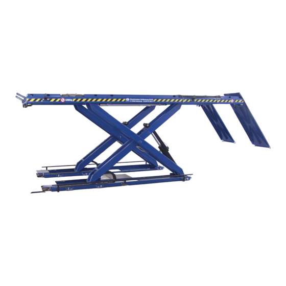
General Information Description The DUO-GN is a scissors lift equipped with runways. In its standard version, the lift has a maximum lifting height of 2075 mm. Intended Use The lift is intended to be used for the safe lifting of automotive vehicles. Be sure to observe the rated load capacity and load distribution. -
Page 10: Specifications
38 l approx. 38 l Petroleum-based fluid HLPD 32 min. HLPD 32 min. HLPD 32 min. specification Biodegradable fluid MAHA HLP 32 MAHA HLP 32 MAHA HLP 32 specification Working pressure max. 260 bar 260 bar 260 bar Pump capacity 3.1 cm... - Page 11 Overview of DUO GN Lift (with Wheel-Free Jack) BA081101-en...
-
Page 12: Sample Nameplate
Sample Nameplate Lifts of this model series have one large and one small nameplate each at the control desk and at the hydraulic power unit. In the event of customer complaints, hotline requests or spare parts orders, serial number and YoM of the lift should always be indicated. SCHERENHEBEBÜHNE Seriennummer / Baujahr: Projekt:... -
Page 13: Power And Air Supply
2.7.3 Power and Air Supply Power supply cable and air hose should be run to the control desk location with an excess length of at least 1.5 m. 2.7.3.1 Power Supply 3~ + N + PE 400 V, 50 Hz. Select a wire size appropriate for lift model and cable length. Motor power in kW Time-delay fuse in A Rated current in A... - Page 14 BA081101-en...
-
Page 15: Operation
Operation Lift operation by trained personnel over 18 years only. Apply the parking brake after positioning the vehicle on the lift. Do not allow anyone to stay in lift area during raising and lowering cycles. Closely watch the vehicle and the lift during raising and lowering cycles. Observe the rated load capacity. -
Page 16: Controls
Controls 3.2.1 Operator's Controls Description Symbol Power (white signal lamp) Lights up once lift is ready for operation. Error (red signal lamp) Lights up or flashes in the event of errors such as light barrier interruptions. Axle Jack Position (orange signal lamp) [optional] Only available with option "Floor Cover with Defined Axle Jack Position". -
Page 17: Main Switch
Raise Wheel-Free Jack (button) [optional] Use this button to raise the wheel-free jack. Lower Wheel-Free Jack (button) [optional] Use this button to lower the wheel-free jack. The availability of the above functions depends on the accessory equipment of your lift. See operating manuals provided. -
Page 18: Operating The Lift
Operating the Lift 3.3.1 Switch-on / Switch-off In case of emergency turn the main switch to position 0. ON: Turn main switch to position 1. The POWER signal lamp lights up once the lift is ready for operation. ... -
Page 19: Raising
3.3.3 Raising Closely watch the vehicle and the lift during raising and lowering cycles. Do not allow anyone to stay in lift area. Be sure lift is in bottom position. Slowly center vehicle on runways. Secure vehicle using parking brake and chocks. ... -
Page 20: Lowering
3.3.6 Lowering Closely watch the vehicle and the lift during raising and lowering cycles. Do not allow anyone to stay in lift area. Press and hold LOWER button until lift has reached desired height. Before starting the lowering cycle the lift will slightly raise to disengage the locking latch. -
Page 21: Hydraulic Inclination
3.3.7 Hydraulic Inclination Optionally available for vehicles with lowered chassis. Do not drive onto or off the runways before they are in fully inclined position. Press and hold ENABLE RUNWAY INCLINATION button until the runways are in fully inclined position. ... -
Page 22: Automatic Runway Synchronization
Automatic Runway Synchronization Two "reference events" are required to ensure proper function of the runway synchronization (optional): Lowering to bottom position to determine the zero point. Raising from bottom position to determine the filling ratio of the cylinder. The procedures explained below serve to activate the automatic runway synchronization. -
Page 23: Lift With Permanent Inclination Device
3.4.3 Lift with Permanent Inclination Device Press and hold the RAISE button until the runway supports become accessible. Remove the supports from under both runways. Lower the lift. After the lift has reached bottom position keep holding the LOWER button for a few seconds. -
Page 24: Cross Member
Cross Member To increase the lift stability, the runways can be optionally equipped with a cross member. Once a certain level difference is exceeded, the cross member will automatically disengage to avoid damage to the lift. Periodically check the cross member for secure engagement (see illustration below, position 1). Engaged position Partially disengaged position Fully disengaged position... -
Page 25: Manual Lowering
Manual Lowering In case of motor defect or power failure the lift can be lowered manually. The lift may only be lowered, not raised. Authorized personnel only! Do not restart the lift before the error has been remedied. Open the solenoid valve first at the slave side cylinder (Y5), then at the master side cylinder (Y4). -
Page 26: Manual Lowering (Lift With Center Cover)
Manual Lowering (Lift with Center Cover) In case of motor defect or power failure the lift can be lowered manually. The lift may only be lowered, not raised. Authorized personnel only! Do not restart the lift before the error has been remedied. Open the solenoid valve (A) first at If required, disengage the safety latches from the slave side cylinder (Y5), then at... -
Page 27: Operation Of Wheel-Free Jack
Operation of Wheel-Free Jack Ensure that the runways and the wheel-free jack are in fully lowered position before driving on or off the lift. 3.8.1 Preparations Center the vehicle over the wheel-free jack. Lift the extensions using the handles (1) and position them (2) under the vehicle lift points. -
Page 28: Manual Lowering
3.8.4 Manual Lowering In case of motor defect or power failure the lift can be lowered manually. The lift may only be lowered, not raised. Authorized personnel only! Do not restart the lift before the error has been remedied. Open the solenoid valve first at the slave side cylinder (Y11), then at the master side cylinder (Y10). -
Page 29: Manual Equalization
3.8.5 Manual Equalization 1 Push and hold the button beneath the control desk. The slave cylinder of the wheel-free jack is now disabled, only the slave cylinder can be operated. 2 Use buttons "Raise WFJ" and "Lower WFJ" to equalize both sides of the wheel- free jack. - Page 30 BA081101-en...
-
Page 31: Maintenance
Maintenance Turn off and lock the main switch before servicing the lift. Annual Inspection The maintenance interval prescribed by the manufacturer is 12 (twelve) months. This maintenance interval refers to normal workshop usage. If the equipment is used more frequently or under severe operating conditions (e.g. -
Page 32: Greasing Points
Greasing Points Cylinders Quarterly grease the cylinder and plunger hinges through lubricator nipples 1.1 and 1.2. Remove waste grease. Lifts equipped with double latch: Also grease the hinges of the pneumatically actuated cylinders for the Set-on-Locks function. Scissors Pins Quarterly grease the scissors pins on the outside and inside through lubricator nipples 2.1 and 2.2. -
Page 33: Greasing Points At The Wheel-Free Jack
Thrust Bearings Quarterly grease the thrust bearings through the lubricator nipples (5). Remove waste grease. Lift should be greased monthly for severe use applications. Greasing Points at the Wheel-Free Jack Tracks inside the Lift Runway Quarterly clean and slightly grease the tracks inside the runway (1). Tracks inside the Wheel-Free Jack Quarterly clean and slightly grease the tracks inside the wheel-free jack (2). -
Page 34: Pneumatic Floor Cover
Pneumatic Floor Cover Only for lifts with pneumatic floor cover: Quarterly clean and grease the plastic guides of the limit stops. Cleaning Do not use high pressure / steam jet cleaners or caustic cleaning agents which attack coatings and sealing materials. Risk of damage! Periodically wash off aggressive substances such as salt water, brake fluid etc. - Page 35 Motor running, but pressure build-up insufficient to raise lift. Manual lowering screw open. Close screw. Hydraulic system leaking. Remove leakage. Low fluid level. Check fluid level, refill as required. Vehicle too heavy. Check vehicle weight, reduce if possible. Repair work on safety devices and electrical equipment by authorized personnel only. The transverse LB apertures (Ø...
-
Page 36: Life Expectancy
Contents of the Declaration of Conformity MAHA Maschinenbau Haldenwang GmbH & Co. KG herewith declares as a manufacturer its sole responsibility to ensure that the product named hereafter meets the safety and health regulations both in design and construction required by the EC directives stated below.
Need help?
Do you have a question about the DUO GN Series and is the answer not in the manual?
Questions and answers