Sign In
Upload
Download
Table of Contents
Contents
Add to my manuals
Delete from my manuals
Share
URL of this page:
HTML Link:
Bookmark this page
Add
Manual will be automatically added to "My Manuals"
Print this page
×
Bookmark added
×
Added to my manuals
Manuals
Brands
MAHA Manuals
Lifting Systems
ECON III 3.0
Technical handbook
MAHA ECON III 3.0 Technical Handbook
Two post lift
Hide thumbs
1
2
Table Of Contents
3
4
5
6
7
8
9
10
11
12
13
14
15
16
17
18
19
20
21
22
23
24
25
26
27
28
29
30
31
32
33
34
35
36
37
38
39
40
41
42
43
44
45
46
47
48
49
50
51
52
53
54
55
56
57
58
59
page
of
59
Go
/
59
Contents
Table of Contents
Bookmarks
Table of Contents
Table of Contents
Specifications
ECON III 3.0 / 3.5 Standard
ECON III 4.0 Standard
ECON III 3.0 / 3.5 with Adapter Plate
ECON III 4.0 with Adapter Plate
ECON III 3.0 with Baseframe
Installation
Standard Delivery
Econ III 3.0
Econ III 3.5
Econ III 4.0
Installation Checklist
Location
Foundation Thickness
Positioning the Columns
Shimming the Baseplates
Standard
With Adapter Plate
Aligning the Columns
Anchoring the Columns
Anchor Installation
Anchor Dimensions
Curing Time
Anchor Installation MKT B12
Electrical Connection
Overhead Cable Installation
Inground Cable Installation
Potential Equalization
Installing the Controller Board
Installing Strain Relief Clips
Connector Pin Assignment and Contactors
Connecting the Power Supply Cord
Installing the Cable Guide and the Motor Covers
Installing the Support Arms
Installing and Checking the Arm Restraints
Installing the Door Protection Strips
Initial Operation
Yellow LED Flashing
Yellow LED Not Flashing
Floor Contact
Namur Leds on Controller Board
Commissioning Checklist
Service Information
Controller Board
LED Display Unit
Connector Pin Assignment
Connector Types
Extensions
Serial Interface
EEPROM Variables
Behavior of Lift Control System
Emergency-Down (Previously "Trial Run")
Performing the Emergency-Down
Load Nut Failure
Floor Contact of Support Arms
Contact with an Obstruction During Lowering Cycles
Motor Speed Error During Raising Cycles
Level Difference between Carriages
Upper End Position
Bottom Position
LED Display Unit
Upper and Lower Proximity Switches
Adjusting the Upper Proximity Switches (Pulse Generators)
Adjusting the Lower Proximity Switches (Limit Switches)
Motor Plate
Support Bearings for Lifting Screw
Upper Bearing
Lower Bearing
Drive Motor
Manual Lowering
Aligning the Pulleys
Maintenance Schedule
Checking the Load Nut for Wear
Greasing the Load Nut
Greasing the Slide Tracks
Greasing the Arm Extensions
Greasing the Disk Adapter Threads
Operational and Wear Checks
Checking the Lift Stability
Advertisement
Quick Links
1
Econ III 3.0 / 3.5 Standard
Download this manual
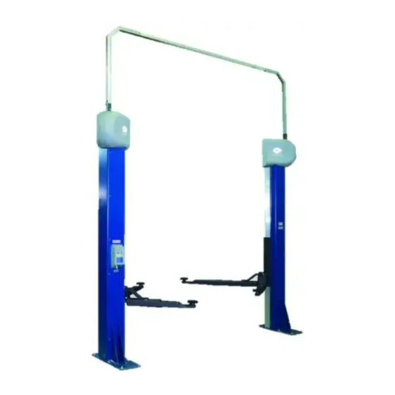
ECON III 3.0 / 3.5 / 4.0
Two Post Lift
Technical Handbook
TH362601-en
Table of
Contents
Previous
Page
Next
Page
1
2
3
4
5
Advertisement
Table of Contents
Need help?
Do you have a question about the ECON III 3.0 and is the answer not in the manual?
Ask a question
Questions and answers
Related Manuals for MAHA ECON III 3.0
Lifting Systems MAHA ES 93 FT Operating Instructions Manual
One post inground lift (27 pages)
Lifting Systems MAHA ECON III 4.0 Technical Handbook
Two post lift (59 pages)
Lifting Systems MAHA ECON II 3.0 Technical Handbook
Two post lift (45 pages)
Lifting Systems MAHA ES Technical Handbook
One/two post inground lifts (80 pages)
Lifting Systems MAHA DUO-GN Technical Handbook
Scissors lift (96 pages)
Lifting Systems MAHA RGE UC Operating Instructions Manual
Mobile column lift (34 pages)
Lifting Systems MAHA HL CS Series Operating Instructions Manual
Two post lifts (23 pages)
Lifting Systems MAHA DUO GN Series Original Operating Instructions
(37 pages)
Lifting Systems MAHA ECON III 5.0 Technical Handbook
Two post lift (49 pages)
Lifting Systems MAHA ZS SQUARE Technical Handbook
One/two post inground lifts (80 pages)
Lifting Systems MAHA MA STAR 3.5 Operating Instructions Manual
Two post lift (22 pages)
Lifting Systems MAHA ZS94 Original Operating Instructions
Barlift, two post inground lifts (35 pages)
Lifting Systems MAHA MLS Series Original Operating Instructions
Weight simulators (30 pages)
Lifting Systems MAHA MA STAR 5.5 Original Operating Instructions
Two post lift (35 pages)
Lifting Systems MAHA CARLIFT 4.1 Technical Handbook
Four post lift for vehicles up to 4,000 kg gross weight (42 pages)
Lifting Systems MAHA ZS SQUARE II 3.5 Original Operating Instructions
Two post lifts with flat head or swing arm supports (52 pages)
This manual is also suitable for:
Econ iii 3.5
Econ iii 4.0
Table of Contents
Save PDF
Print
Rename the bookmark
Delete bookmark?
Delete from my manuals?
Login
Sign In
OR
Sign in with Facebook
Sign in with Google
Upload manual
Upload from disk
Upload from URL


Need help?
Do you have a question about the ECON III 3.0 and is the answer not in the manual?
Questions and answers