MAHA MA STAR 5.5 Original Operating Instructions
Two post lift
Hide thumbs
Also See for MA STAR 5.5:
- Operating instructions manual (22 pages) ,
- Original operating instructions (36 pages)
Table of Contents
Advertisement
Quick Links
Advertisement
Table of Contents

Related Manuals for MAHA MA STAR 5.5


Summary of Contents for MAHA MA STAR 5.5
- Page 1 MA STAR 5.5 Two Post Lift Original Operating Instructions BA364601-en...
- Page 2 BA364601-en 2021-07-12 © MAHA Maschinenbau Haldenwang GmbH & Co. KG The reproduction, distribution and utilization of this document as well as the communication of its contents to others without explicit authorization is prohibited. Offenders will be held liable for the payment of damages.
-
Page 3: Table Of Contents
Intended Use ........................8 2.2.3 Overall View with Components ..................9 Technical Data ......................10 2.3.1 Technical Data MA STAR 5.5 Standard ..............10 2.3.2 Installation Diagram MA STAR 5.5 Standard ............. 11 2.3.3 Safety Zone MA STAR 5.5 Standard ................12 2.3.4... - Page 4 Safety Information ......................23 Intuitive Control and Operating States ................ 25 Preparations ........................26 4.3.1 Initial Position/Ready for Operation ................26 4.3.2 Positioning of the Vehicle .................... 26 4.3.3 Positioning of the Support Arms and Support Discs ..........27 4.3.4 Support Disc Raisers ....................
-
Page 5: General Safety Instructions
General Safety Instructions Introduction • These operating instructions must be read carefully and understood before work commences. • Please observe the specific safety information provided for the respective sections of the operating instructions. • Adhering to the procedures, sequences and corresponding safety instruc- tions is essential. -
Page 6: What To Do In The Event Of Defects Or Malfunctions
What to Do in the Event of Defects or Malfunctions • If a malfunction occurs, e.g. uncontrolled raising and lowering or in the case of load-bearing components of the structure becoming deformed, immedi- ately lower the lift to the ground to its initial position or support the structure. •... -
Page 7: Description
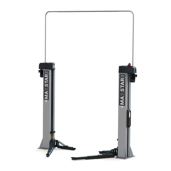
2.2.1 Design and Basic Functions The MA STAR 5.5 two post lift consists, among other components, of two edged, welded column profiles with base plate. The base plates ensure the columns are securely anchored to the ground. The column profile bears the weight of the lifted vehicle, accommodating the lifting carriage on the inner panel and the control unit on the outer panel. -
Page 8: Intended Use
2.2.2 Intended Use • This lift is exclusively intended for the safe lifting and lowering of passenger cars and commercial vehicles up to a total weight of 5.5 t within the scope of maintenance and repair work. • In compliance with the load distribution regulations of DIN EN 1493, the per- mitted load capacity on the identification plate must not be exceeded. -
Page 9: Overall View With Components
2.2.3 Overall View with Components A Control column a Toothed belt drive B Opposite column b Trapezoidal spindle C Cable bridge c Nut package d Lifting carriage (with support arm D Control unit brackets) E Drive motor Support arms e Support arm lock G Connector plug BA364601-en... -
Page 10: Technical Data
Technical Data 2.3.1 Technical Data MA STAR 5.5 Standard Total height [HG]................... 5193 mm Total width [BG] ..................4200 mm* Clear height [HL] ................... 5146 mm Column height [HS] ..................3243 mm Vertical travel [HW] ..................2000 mm Length of stroke max. [HO] ................2115 mm Pivoting height [HU].................. -
Page 11: Installation Diagram Ma Star 5.5 Standard
2.3.2 Installation Diagram MA STAR 5.5 Standard BA364601-en... -
Page 12: Safety Zone Ma Star 5.5 Standard
2.3.3 Safety Zone MA STAR 5.5 Standard 3530 mm* 1000 mm 1000 mm * Dimension refers to the drive-through width of 2630 mm. BA364601-en... -
Page 13: Technical Data Ma Star 5.5 Slim
2.3.4 Technical Data MA STAR 5.5 Slim Total height [HG]................... 5193 mm Total width [BG] ..................4100 mm* Clear height [HL] ................... 5146 mm Column height [HS] ..................3243 mm Vertical travel [HW] ..................2000 mm Length of stroke max. [HO] ................2115 mm Pivoting height [HU].................. -
Page 14: Installation Diagram Ma Star 5.5 Slim
2.3.5 Installation Diagram MA STAR 5.5 Slim BA364601-en... -
Page 15: Safety Zone Ma Star 5.5 Slim
2.3.6 Safety Zone MA STAR 5.5 Slim 3430 mm* 1000 mm 1000 mm * Dimension refers to the drive-through width of 2530 mm. BA364601-en... -
Page 16: Technical Data Ma Star 5.5 Wide
2.3.7 Technical Data MA STAR 5.5 Wide Total height [HG]................... 5193 mm Total width [BG] ..................4350 mm* Clear height [HL] ................... 5146 mm Column height [HS] ..................3243 mm Vertical travel [HW] ..................2000 mm Length of stroke max. [HO] ................2115 mm Pivoting height [HU].................. -
Page 17: Installation Diagram Ma Star 5.5 Wide
2.3.8 Installation Diagram MA STAR 5.5 Wide BA364601-en... -
Page 18: Safety Zone Ma Star 5.5 Wide
2.3.9 Safety Zone MA STAR 5.5 Wide 3680 mm* 1000 mm 1000 mm * Dimension refers to the drive-through width of 2780 mm. BA364601-en... -
Page 19: Control Description
Control Description The lift is operated at the control unit with two push buttons. These have arrows, which show the direction of movement. Their blue light, which activates according to operating status and possible directions of movement, enables intuitive operation of the lift. Above the two control buttons is a fault indicator, which is backlit in either a flashing or continuous red in the case of a malfunction. -
Page 20: Transport, Handling And Storage
Transport, Handling and Storage Safety Information WARNING • Wear personal protective equipment. • Standing under a suspended load is prohibited. • The transport and storage of packages is only permitted using original transport racks. Observe the max. stacking height. • Before removing the packaging straps, secure the packages against falling and maintain a safe distance. -
Page 21: Packaging Information
Packaging Information 3.3.1 Packaging MA STAR 5.5 Dimensions (1st and and 2nd package) (L x W x H) .... 3185 x 760 x 960 mm Weight (1st package) ..................796 kg Weight (2nd package) .................. -
Page 22: Storage
Lift in transport rack on pallet, pick-up points marked Storage The packages must be stored in a covered location and protected from direct sunlight. They must be stored at low humidity and at a temperature between 0 °C and +40 °C. The lifts may only be stacked in the original transport racks, there is a two-lift maximum stacking height (see also section “Transport and Handling”). -
Page 23: Operation
Operation Safety Information WARNING • Observe the detailed operating instructions. • Comply with legal accident prevention regulations. • Wear personal protective equipment. • Carry out visual and operational checks daily before the commencement of work (see also section “Test and Maintenance Schedule”). •... - Page 24 the load during the raising and lowering process. • Monitor the load and the lift during raising and lowering. In the event of an irregularity, the emergency stop button (main button on the main operating column or the emergency stop button on the second control unit on the op- posite column), must be pressed immediately.
-
Page 25: Intuitive Control And Operating States
Intuitive Control and Operating States The lift has been fitted with an intuitive operating system. Depending on the operating status, illuminated buttons provide a visual indication of the lift’s available options regarding direction of movement. Lift switched When Only raising Raising and Only lowering Fault, lift not... -
Page 26: Preparations
Preparations 4.3.1 Initial Position/Ready for Operation • The main switch must be at position 0. • The lift must be fully lowered. • The support arms must be pivoted completely away from the working area (initial position, see diagram.) 4.3.2 Positioning of the Vehicle •... -
Page 27: Positioning Of The Support Arms And Support Discs
4.3.3 Positioning of the Support Arms and Support Discs • Swivel and extend the support arms to position the support discs under the pick-up points specified by the vehicle manufacturer. • Turn the support discs so that all four pick-up points are accessed evenly. 4.3.4 Support Disc Raisers •... -
Page 28: Raising And Lowering Cycles
Raising and Lowering Cycles 4.4.1 Inspection of the Load Pick-up Points and Support Arm Locks • Set the main switch to position 1. After an initial flashing of all three lights, the UP button is permanently lit. • Press the UP button until the support discs are in contact with the pick-up points of the vehicle. -
Page 29: Lowering Process And Ce Stop
4.4.3 Lowering Process and CE Stop • Before lowering the vehicle, remove tools, support stands or similar obsta- cles from the working area of the lift. The operator is responsible for ensuring that nobody is within the danger ar- • Press and hold the lit DOWN button until the desired lifting height is reached. •... -
Page 30: Inspection And Maintenance
Inspection and Maintenance Safety Information WARNING • The relevant health and safety regulations must be observed. • Wear personal protective equipment. • Service work may only be carried out by authorised service technicians. • Repairs, maintenance and set-up work may only be carried out when the ma- chinery is stationary. - Page 31 • Check support arm extensions for free movement, lubricate as required. • Check support discs for damage, replace as necessary. • Check threads of support discs for free movement, lubricate as required. • Visual check of all accessible welding seams Annually •...
-
Page 32: Care Instructions
Care Instructions • Periodically clean the equipment and treat it with a care product. • Repair damage to the paintwork immediately to prevent corrosion. • Do not use caustic cleaning agents or high pressure and steam jet cleaners to avoid equipment damage. Regular care and maintenance is the key condition for functionality and long life expectancy of the equipment! Troubleshooting... -
Page 33: Error Chart
Error Chart Display Diagnostics Remedy Button pressed by mistake. Release button. Signal sound immediately Control panel has short upon switching on. Notify service team. circuit. Lift can only move upwards. If necessary, the lower end Lift has reached its end position can be adjusted to The lift stops when position. -
Page 34: Repairs
Display Diagnostics Remedy DOWN button and UP button and red fault Configuration mode. Notify service team. indicator flash more than 10 times. Red fault indicator flashes, Electrical emergency stop Lower the lift. blue DOWN button is lit. activated. Turn off main switch and Red fault indicator light and switch on again after approx. - Page 35 MAHA Maschinenbau Haldenwang GmbH & Co. KG, Hoyen 20, 87490 Haldenwang, Germany Haldenwang, 2021-07-12 Andreas Maier Head of Mechanical Development MAHA Maschinenbau Haldenwang GmbH & Co. KG ꞏ Hoyen 20 ꞏ 87490 Haldenwang ꞏ Germany Phone +49 8374 585-0 | Fax +49 8374 585-590 | Mail maha@maha.de | Web www.maha.de...
Need help?
Do you have a question about the MA STAR 5.5 and is the answer not in the manual?
Questions and answers