Table of Contents
Advertisement
Quick Links
IM-A-1283K January 2024
INSTRUCTION MANUAL
CTRS-100A
Compact Recorder
【HARDWARE】
Thank you for purchasing this KYOWA's product.
Read this instruction manual carefully in order to make full use of the high-performance
capabilities of the product. Do not use the product in methods other than described in this
instruction manual.
Note that this instruction manual mainly describes how to handle the hardware.
For details on the software, see the control software instruction manual.
In general, the company and product names indicated in this instruction manual are
trademarks or registered trademarks of each company.
Copying or otherwise reproducing this product in whole or in part without permission is
prohibited.
This product is copyrighted material of Kyowa Electronic Instruments Co., Ltd., and all
associated copyrights belong to Kyowa Electronic Instruments Co., Ltd.
The details of this instruction manual are subject to change without notice.
Advertisement
Table of Contents

Subscribe to Our Youtube Channel
Related Manuals for KYOWA CTRS-100A


Summary of Contents for KYOWA CTRS-100A
- Page 1 Copying or otherwise reproducing this product in whole or in part without permission is prohibited. This product is copyrighted material of Kyowa Electronic Instruments Co., Ltd., and all associated copyrights belong to Kyowa Electronic Instruments Co., Ltd. The details of this instruction manual are subject to change without notice.
- Page 2 (Blank page)
-
Page 3: Table Of Contents
1. PRODUCT OVERVIEW ................... 1-1 Product Overview....................1-1 System Configuration ..................1-5 Controls and Indicators ..................1-6 1-3-1. Compact Recorder: CTRS-100A ..............1-6 1-3-2. Remote Control Unit: CTRS-RCU010A ............. 1-10 1-3-3. Strain / Voltage Unit: CTRS-CDV010A ............1-15 1-3-4. Voltage Unit: CTRS-CVPS010A ..............1-15 1-3-5. - Page 4 CONTENTS CTRS-CDV010A Wiring Method ..............2-16 CTRS-CVPS010A Wiring Method ..............2-17 CTRS-CTA010A Wiring Method ..............2-21 2-6-1. Attaching and removing the Temperature measuring adapter ....2-21 2-6-2. Connection to terminal block ..............2-22 CTRS-SYNC010A Wiring Method ..............2-24 2-7-1. SYNC IN connector .................. 2-24 2-7-2.
- Page 5 5-1-1. File closing function ..................5-1 5-1-2. Data protection function during power interruption ........5-2 5-1-3. Recording resumption function..............5-4 Input Resistance check function (CTRS-100A, CTRS-CDV010A) .....5-7 Burnout check function (CTRS-CTA010A) ............5-9 Communication Speed Survey (CTRS-CAG010A) .......... 5-11 Can Output Test (CTRS-CAG010A) ..............5-13...
- Page 6 CTRS-CAG010A Details ................. 6-10 CTRS-CAG011A Details................6-12 7. MAINTENANCE ....................... 7-1 Maintenance Details ..................7-1 Initializing the CTRS-100A ................7-3 8. PRODUCT SPECIFICATIONS ................. 8-1 CTRS-100A Product Specifications ..............8-1 CTRS-RCU010A Product Specifications ............8-5 CTRS-CDV010A Product Specifications ............8-6 CTRS-CVPS010A Product Specifications ............
- Page 7 CONTENTS CTRS-CDV010A External Views................9-2 CTRS-CVPS010A External Views ..............9-2 CTRS-CTA010A External Views ................9-3 CTRS-SYNC010A External Views ..............9-3 CTRS-BATT010A External Views ..............9-4 CTRS-WLAN010A/011A/012A External Views ..........9-4 CTRS-CAG010A External Views ...............9-5 CTRS-CAG011A External Views ..............9-5 10. TECHNICAL INFORMATION ................10-1 Cable calibration value ................... 10-1 11.
- Page 8 CONTENTS (Blank page)
-
Page 9: Standard Accessories
USB cable Ballpoint screwdriver Stack-connector caps (for female) Input connector cap * It is mounted on CTRS-100A at the time of shipment. Remote Control Unit: CTRS-RCU010A Name Quantity "READ BEFORE USING THE PRODUCT" document "Terms and Conditions of New Product Warranty"... - Page 10 STANDARD ACCESSORIES Strain/Voltage Unit: CTRS-CDV010A Name Quantity READ BEFORE USING THE PRODUCT" document "Terms and Conditions of New Product Warranty" document Stack-connector caps (for female) Stack-connector caps (for male) Input connector cap * It is mounted on CTRS-CDV010A at the time of shipment. Voltage Unit: CTRS-CVPS010A Name Quantity...
- Page 11 STANDARD ACCESSORIES Synchronization Unit: CTRS-SYNC010A Name Quantity "READ BEFORE USING THE PRODUCT" document "Terms and Conditions of New Product Warranty" document Stack-connector caps (for female) Stack-connector caps (for male) * It is mounted on CTRS-SYNC010A at the time of shipment. Battery Unit: CTRS-BATT010A Name Quantity...
- Page 12 STANDARD ACCESSORIES CAN Unit: CTRS-CAG010A Name Quantity "READ BEFORE USING THE PRODUCT" document "Terms and Conditions of New Product Warranty" document Stack-connector caps (for female) Stack-connector caps (for male) * It is mounted on CTRS-CAG010A at the time of shipment. CAN/GPS Unit: CTRS-CAG011A Name Quantity...
-
Page 13: Optional Accessories
OPTIONAL ACCESSORIES OPTIONAL ACCESSORIES The optional accessories are listed below. Compact Recorder: CTRS-100A CTRS AC adapter UIA345-12-L-JP CTRS AC adapter (for US) UNI345-1238-L-US Various measuring units Various expansion units Remote control unit CTRS-RCU010A SD card 4 GB,16 GB EXTERNAL I/O cable... - Page 14 OPTIONAL ACCESSORIES Synchronization Unit: CTRS-SYNC010A CTRS Communication cable (3 m) N-131 CTRS Sync cable (2 m) N-130 Connector cap BRA.1B.200.PCSG (For the synchronous input connector / synchronous output connector) Battery Unit: CTRS-BATT010A CTRS DC power cable (1.8 m) P-79 CTRS AC adapter UIA345-12-L-JP CTRS AC adapter (for US) UNI345-1238-L-US...
-
Page 15: Safety Precautions
Prior to use To ensure safe use of this product, be sure to read the safety precautions before use. Kyowa Electronic Instruments Co., Ltd., assumes no liability for any damage resulting from the user's failure to comply with the safety precautions. - Page 16 SAFETY PRECAUTIONS WARNING ● Power supply ・ To prevent fire hazards, before turning on the product, make sure the power-supply voltage specified for the product matches the local line voltage ・ If using the CTRS DC power cable P-79, be careful about the wiring polarity. Connecting the power polarity in reverse may cause accidents or malfunctions.
- Page 17 ● Supported input (CTRS-100A,CTRS-CDV010A) ・ CTRS-100A and CTRS-CDV010A support strain/voltage measurement. When measuring strain, connect only transducers and bridge boxes that use strain gauges. Do not input signals outside the input range.
- Page 18 SAFETY PRECAUTIONS WARNING ● Supported input (CTRS-CTA010A) ・ CTRS-CTA010A is a measuring instrument dedicated to thermocouples. Do not connect anything other than a thermocouple. Failure to do so may cause electric shock, performance degradation, or failure. ● Supported input (CTRS-CAG010A) ・...
- Page 19 ● Do not use wireless LAN in medical facilities. It may cause malfunction of medical equipment and may be life-threatening. Turn off the WIRELESS switch or remove Wireless LAN unit from the CTRS-100A. ● Do not use wireless LAN in aviation facilities and aircraft.
- Page 20 SAFETY PRECAUTIONS CAUTION ● Use the product in a temperature range of -10 to 50 ℃. ・ Using the product at temperatures outside of the specified range may lower product performance or result in malfunctions. If the product must be used under direct sunlight or in a cold place, protect the product with a screen or take proper measures to keep it warm.
- Page 21 SAFETY PRECAUTIONS CAUTION ● Avoid installing sensors near a welding machine or performing measurements near a welding machine. ・ Failure to observe this precaution may result in output abnormalities, erratic operations, or malfunctions. ● Take care when operating this product in high or low pressure environments. ・...
- Page 22 SAFETY PRECAUTIONS CAUTION ● Do not remove SD card while the SD card access LED is lit. ・ Remove SD card while the SD card access LED is lit, it may cause data corruption or SD card failure. ● Do not disconnect the communication cable during data collection. ・...
-
Page 23: Precautions Regarding Wireless Communication
PRECAUTIONS REGARDING WIRELESS COMMUNICATION PRECAUTIONS REGARDING WIRELESS COMMUNICATION ● General notes ・ Depending on your environment, you may not be able to communicate, please be sure to check the communication before use. ・ Communication may not be possible near metal objects, in areas with a lot of metal powder, or surrounded by metal walls. - Page 24 PRECAUTIONS REGARDING WIRELESS COMMUNICATION ● Precautions regarding laws and regulations (CTRS-WLAN010A) ・ This instrument has been certified as a low power radio station in accordance with the Radio Law of Japan. Therefore, you do not need a radio station license to use this instrument.
-
Page 25: Limited Lifespan Parts And Preventive Maintenance
To prevent such problems, perform inspections/maintenance and replace parts as needed. The limited lifespan parts used in the product and optional accessories are as follows: ● Backup battery (CTRS-100A, built-in) ● Lithium-ion battery (CTRS-BATT010A, built-in) ● AC adapter (optional accessory) ●... -
Page 26: Notations Of The Instruction Manual
NOTATIONS OF THE INSTRUCTION MANUAL NOTATIONS OF THE INSTRUCTION MANUAL Notations used in the instruction manual The compact recorder CTRS-100A and various units are collectively called "this equipment". Cautionary and reference notes The notations below are used to attract your attention to important cautionary and reference notes when handling the product. -
Page 27: Product Overview
● Remote Control Unit: CTRS-RCU010A CTRS-RCU010A is a remote control unit for CTRS-100A. By connecting to the CTRS-100A, you can operate even if it is installed out of reach. In addition, buzzer function, various display LEDs and the OPTION button can be used to enhance the operability of the CTRS-100A. - Page 28 CTRS-CDV010A is a measurement unit that equipped with analog front end for strain/voltage measurement. This instrument is equipped with 4 input channels. By connecting to CTRS-100A, you can be expanded to maximum of 32 measurement channels. ● Voltage Unit: CTRS-CVPS010A CTRS-CVPS010A is a measurement unit with an analog front-end for voltage measurement.
- Page 29 ● Wireless LAN Unit: CTRS-WLAN010A/011A/012A CTRS-WLAN010A/011A/012A is an expansion unit for connecting the CTRS-100A to a PC via wireless LAN. The radio frequency selected from GHz and GHz.
- Page 30 ● CAN Unit: CTRS-CAG010A CTRS-CAG010A is an expansion unit that can be connected to the CTRS-100A to add CAN ports. In addition to conventional CAN, CAN FD is supported. By using the CTRS-CAG010A together with the CTRS-100A series measurement unit, both analog input signals and CAN data can be measured simultaneously.
-
Page 31: System Configuration
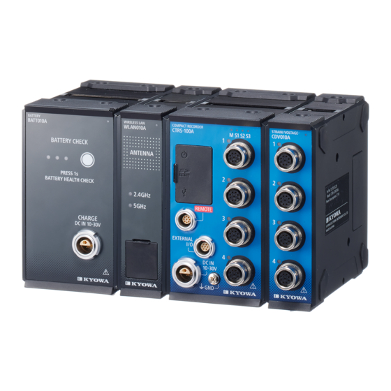
System Configuration System Configuration The figure below shows an example of system configuration. CTRS-BATT010A CTRS-100A CTRS-CDV010A ・Bridge box ・Strain-gage transducer ・Analog voltage, etc. USB cable SD card (control software) DC power supply or AC adapter Remote Control Unit: CTRS-RCU010A Example of a 32-channel strain/voltage measurement system configuration... -
Page 32: Controls And Indicators
Controls and Indicators Controls and Indicators 1-3-1. Compact Recorder: CTRS-100A ⑬ Top view ① ⑧ ② ③ ⑨ ⑫ ④ ⑩ ⑤ ⑥ ⑦ ⑪ Side view Front view ① Power switch Switch for turning on/off the power supply of this equipment. - Page 33 30 VDC. Connect the included DC power cable or an AC adapter (optional accessory). ⑧ Status LEDs Display the CTRS-100A status. For details on the lighting patterns and states, see "Table 1-1. Status LED display" on page 1-8. ⑨ Channel status LEDs Display the status of each channel.
- Page 34 Controls and Indicators Status LED display The LEDs that display the status change depending on the CTRS-100A operating conditions. 1. For non-synchronous operation (standalone operation) The status is displayed at the M (master) LED. 2. For synchronous operation (master operation) The status is displayed at the M (master) LED.
- Page 35 Controls and Indicators Channel status LED display The status is displayed as shown below. Table 1-2. Channel status LED display LED display Status Status details Lit up On standby Monitoring or recording can be started. Flashing Recording Indicates that data is being recorded. Blue Flashing Executing balance...
-
Page 36: Remote Control Unit: Ctrs-Rcu010A
Rear view Front view ①Status LEDs Display the CTRS-100A status. The lighting patterns are the same as the CTRS-100A status LEDs. For details, see "Table 1-1. Status LED display" on page 1-8. ② Remaining-SD-card-space indicator LED Lights up when the remaining SD card space is low. For details, see “Table 1-3. - Page 37 Controls and Indicators ⑤ REC button Press this once to start recording. For details on the LED lighting pattern and status, see Table 1-6. REC LED display on page 1-12. ⑥ STOP button Press this twice to stop recording. The operating method can be changed to pressing this once with the control software setting.
- Page 38 Controls and Indicators Table 1-4. Remaining-battery-power indicator LED display LED display Status Status details Normal The remaining battery charge is normal. Remaining The remaining battery charge is less than 30%. Flashing charge Charge the battery before its energy runs out. caution Recording is not possible because the battery has run out of Flashing...
- Page 39 Controls and Indicators Table 1-8. READ LED display LED display Status Status details It is turned off when the measurement condition file is not read from the SD card. Indicates that the measurement condition file has been read Blue Lit up Read success correctly from the SD card.
- Page 40 For details, refer to the item related to the remote control in "4 ENVIRONMENT SETTINGS" in the operation manual of the control software DCS-100A [CTRS-100A Operations]. (The initial setting is to press the button twice.) ●...
-
Page 41: Strain / Voltage Unit: Ctrs-Cdv010A
③ ② Channel status LEDs Display the status of each channel. The lighting patterns are the same as those of the CTRS-100A channel status LEDs. For details, see "Table 1-2. Channel status LED display" on page 1-9. ③ Input connectors Connectors for inputting a strain-gage transducer, bridge box, analog voltage, etc. -
Page 42: Thermocouple Unit: Ctrs-Cta010A
Controls and Indicators 1-3-5. Thermocouple Unit: CTRS-CTA010A ① Status LED ① Displays the CTRS-CTA010A status. For details on the lighting patterns, see "Table 1-9. Status LED ② ③ display for Measurement Units" on page 1-16. ② Temperature measurement adapter A temperature measurement adapter with an internal reference contact compensation function. -
Page 43: Synchronization Unit: Ctrs-Sync010A
Controls and Indicators 1-3-6. Synchronization Unit: CTRS-SYNC010A ① Status LED ① ② Displays the CTRS-SYNC010A status. The lighting ③ patterns are the same as those of the CTRS- CDV010A status LED. For details, see "Table 1-10. Status LED display for expansion unit" on page 1- ④... - Page 44 Controls and Indicators Table 1-10. Status LED display for expansion unit Color Power Lighting Status Stetus detail Recording supply pattern External Normal Blue power Lit up The equipment is operating normally. operation supply Possible Buttery Normal Purple Lit up The equipment is operating normally. unit operation External...
-
Page 45: Battery Unit: Ctrs-Batt010A
Controls and Indicators 1-3-7. Battery Unit: CTRS-BATT010A ① ③ ② ④ ① Status LED Displays the CTRS-BATT010A status. Lights / blinks purple when the battery is operated by the battery unit. For details on the lighting pattern and status, see "Table 1-12. Status LED display for battery unit" on page 1-20. - Page 46 70 to 100% when the battery-check switch is pressed or ● ● / - Blue 30 to 69% when operating the CTRS-100A by using ● / - / - Blue 6 to 29% battery power. ☼ / - / -...
- Page 47 Controls and Indicators 3. Charge-status display Lighting Charge Color lit pattern status The charge status is displayed during Charging ● ● ● Blue charging. complete ☼ ● ● Blue 70 to 99% ☼ ● / - Blue 30 to 69% ☼...
-
Page 48: Wireless Lan Unit: Ctrs-Wlan010A/011A/012A
Controls and Indicators 1-3-8. Wireless LAN Unit: CTRS-WLAN010A/011A/012A ① ② ③ ④ ⑥ ⑤ ①Status LED Displays the status of CTRS-WLAN010A / 011A / 012A. The lighting pattern is the same as the status LED of CTRS-SYNC010A. See "Table 1-10. Status LED display for expansion unit"... -
Page 49: Can Unit: Ctrs-Cag010A
Controls and Indicators 1-3-9. CAN Unit: CTRS-CAG010A ① ② ③ ① Status LED Displays the status of CTRS-CAG010A. See "Table 1-13. Status LED display for CAN unit " on page 1-24. ② Port status LED Displays the status each port. See "Table 1-14. Port status LED display for CAN unit " on page 1-24. - Page 50 Controls and Indicators Table 1-13. Status LED display for CAN unit Color Power Lighting Status Stetus detail Recording supply pattern Normal Lit up The equipment is operating normally. External operation Blue power CAN overflow has occurred. Refer to “4-8- Flashing supply Note 3.Number of messages that can be received...
-
Page 51: Can/Gps Unit: Ctrs-Cag011A
Controls and Indicators 1-3-10. CAN/GPS Unit: CTRS-CAG011A ① ② ③ ④ ⑤ ① Status LED Displays the status of CTRS-CAG011A. See "Table 1-13. Status LED display for CAN unit " on page 1-24. ② Port status LED Displays the status each port. See "Table 1-14. Port status LED display for CAN unit " on page 1-24. - Page 52 Controls and Indicators Table 1-15. GPS status LED display LED display Status Status detail Stopping GPS function is disabled. Indicates that GPS data is being received and positioning Lit up Positioning is in progress. Blue Monitoring/Recording Indicates that data is being monitored/recorded with GPS Flashing (Positioning) data being received and potioning.
-
Page 53: Installation Method
This section explains the preparatory work necessary from installation to measurement. Follow the procedure below. Section Connect a measuring unit or expansion unit to Unit Connection … the CTRS-100A as necessary. ↓ Section Connect to a DC power supply, AC adapter, or Power connector …... -
Page 54: Unit Connection
Unit Connection Unit Connection To connect each unit, turn off the CTRS-100A power supply and then perform the procedure below. ① Connect the CTRS-100A to the connection connectors of each units. Connect each measuring unit to the right side of the CTRS-100A, and connect each expansion unit to the left side. - Page 55 Unit Connection ② Use the included ballpoint driver to tighten the connection bolts on the top and bottom and fasten the units to each other. Connection bolts Insert the ballpoint driver and tighten the connection bolts. CAUTION ● Be sure to tighten the top and bottom connection bolts when connecting each unit, as failure to do so may cause performance degradation, malfunctions, or breakage.
- Page 56 Unit Connection ③ If necessary, connected units can be fixed to a base, etc. Each unit has utility nuts, so use M4 screws to fasten them down. The effective depth of the utility nuts is 7 mm. Use screws that have a length equal to (the base thickness) + (5 to 7 mm). For details on the utility nuts, see "5-7.
-
Page 57: Ctrs-100A Wiring Method
CTRS-100A Wiring Method CTRS-100A Wiring Method 2-3-1. Power connector If using a DC power supply Confirm the power-supply voltage before connecting the DC power cable. The acceptable range for the power-supply voltage is 10 VDC to 30 VDC. Make sure the DC power-supply voltage is within the allowable range. - Page 58 CTRS-100A Wiring Method CAUTION ● Applying power supply voltage outside the power-supply voltage range or reversing the connection of the power supply polarity could cause malfunctions or accidents. Be sure not to do this. ● Be sure to ground the GND terminal. If it is not grounded, it could cause electric shocks, performance degradation, or malfunctions.
- Page 59 CTRS-100A Wiring Method If using an AC adapter (optional accessory: UIA345-12-L-JP or UNI345-1238-L-US) Confirm the power-supply voltage before connecting the AC plug of the AC adapter to a power outlet. The power-supply voltage can be checked by doing the following: AC power outlet ①...
- Page 60 CTRS-100A Wiring Method After checking the power supply voltage, connect the AC adapter to the power connector. 100 to 240 VAC To power connector AC adapter (optional accessory) Be sure to ground the GND terminal. CAUTION ● The acceptable range for the power supply voltage for the AC adapter is 100 to 240 VAC.
-
Page 61: Remote Control Connector
CTRS-100A Wiring Method 2-3-2. Remote control connector The connector for connecting the remote control unit CTRS-RCU010A. To remote control connector CTRS-RCU010A Connect the CTRS-RCU010A cable to the connector labeled as REMOTE . 2-3-3. USB connector When connecting to a PC, use the included USB cable to connect to a USB connector. -
Page 62: External I/O Connector
CTRS-100A Wiring Method 2-3-4. External I/O connector Connect the EXTERNAL I/O cable (optional accessory) to use external I/O functions. The pin assignments and signals are shown below. For details on external I/O functions, see "4-4. External I/O" on page 4-21. -
Page 63: Input Connector
If necessary, use the U-136 (optional accessory). Perform monitoring before recording data, and—if there is a lot of noise—try grounding the bridge box grounding terminal or connecting to the CTRS-100A GND terminal and use whichever one has less noise. - Page 64 CTRS-100A Wiring Method If directly connecting a bridge box or strain-gage transducer Hold this part and push it in at connection. It automatically locks. Bridge box strain-gage transducer Hold this part and pull it toward you at removal. If using the U-136 (optional accessory)
- Page 65 Applying excessive force to the cable could cause a disconnection, connector breakage, etc. NOTE ● The H terminal of each CTRS-100A and CTRS-CDV010A channel is the input terminal for TEDS signals. Connecting other signals to this terminal may cause malfunctions.
- Page 66 ● Never input voltage exceeding the absolute maximum rating. Doing so may cause electric shocks, performance degradation, equipment malfunctions, etc. In the voltage measurement mode, the absolute maximum rating of the CTRS-100A and CTRS-CDV010A input is ±70 V. | 2-14...
- Page 67 CTRS-100A Wiring Method When connecting a voltage output type sensor that requires a sensor power supply Use the bridge excitation as the power supply for the sensor. The bridge excitation can be switched between 2 VDC and 5 VDC, and ±1 V / ±2.5 V is output for each GND level.
-
Page 68: Ctrs-Cdv010A Wiring Method
U-136 AMA-A relay cable * The figure shows an example of connecting the AMA-A-2 or AMA-A-5. In addition, in the CTRS-100A analog channel settings, specify measurement mode: voltage (5 V). ● The AMA-A relay cable differs depending on the capacity. -
Page 69: Ctrs-Cvps010A Wiring Method
CTRS-CVPS010A Wiring Method CTRS-CVPS010A Wiring Method The input connector pin assignments are shown below. Signal name sensor power output input - input + GND(FG) Not connected Not connected TEDS+ TEDS-/COM The input circuit of CTRS-CVPS010A is insulated as follows. 2-17 |... - Page 70 CTRS-CVPS010A Wiring Method If the output terminal of the device to be measured is a BNC connector, use the 4109P- BNC plug U-137 (optional accessory) to connect to the instrument. Equipment to be measured U-137 BNC connector When using a general BNC cable, use the 4109P-BNC jack U-129 (optional accessory) to connect to this unit.
- Page 71 CTRS-CVPS010A Wiring Method The following is a wiring example for supplying power to a sensor such as a MEMS sensor. If the connector on the sensor side has 7 pins, use U-136 (optional accessory). Sensor power output Input - Input + GND (FG) Not connected Not connected...
- Page 72 CTRS-CVPS010A Wiring Method COUTION ● Never input a voltage that exceeds the absolute maximum rating. There is a risk of electric shock, performance degradation, equipment failure, etc. The absolute maximum rating of the + and-inputs of the CTRS-CVPS010A is ± 70 V.
-
Page 73: Ctrs-Cta010A Wiring Method
CTRS-CTA010A Wiring Method CTRS-CTA010A Wiring Method 2-6-1. Attaching and removing the Temperature measuring adapter The temperature measuring adapter CT-3A-4 is fixed to CTRS-CTA010A with two hexagon socket head cap screws. Use the ballpoint screwdriver provided with the CTRS- 100A or a 2 mm hex wrench to install and remove. NOTE ●... -
Page 74: Connection To Terminal Block
CTRS-CTA010A Wiring Method 2-6-2. Connection to terminal block The pin layout of the terminal block is as follows. Signal name ① ① CH1+ ② ② ③ CH1- ④ ③ CH2+ ⑤ ⑥ ④ CH2- ⑦ ⑤ ⑧ CH3+ ⑨ ⑥ CH3-... - Page 75 CTRS-CTA010A Wiring Method NOTE ● Make sure that the (+) and (-) of the thermocouple are connected correctly. ● If the core wire protrudes significantly from the terminal block, the internal reference contact accuracy may deteriorate. Remove the coating so that the core wire does not protrude from the terminal block.
-
Page 76: Ctrs-Sync010A Wiring Method
CTRS-SYNC010A Wiring Method CTRS-SYNC010A Wiring Method 2-7-1. SYNC IN connector If connecting a LAN, use the CTRS communication cable N-131 (optional accessory) as shown in the figure below. N-131 To SYNC IN connector CAUTION ● When removing the CTRS communication cable, do not pull on the cable part. -
Page 77: Sync Out Connector
To CTRS-SYNC010A Green bend relief CAUTION ● Be sure the CTRS-100A power is off before inserting or removing the CTRS sync cable. If the power is on when this is done, it may cause the CTRS- SYNC010A to malfunction. ● When removing the cable, do not pull on the cable part. -
Page 78: Ctrs-Cag010A Wiring Method
CTRS-CAG010A Wiring Method CTRS-CAG010A Wiring Method The pin layout of the CAN input connector is as follows. Signal name CAN_H CAN_L CAN_GND Model name: ECB 1B 303 CLN Manufacture: LEMO It can be converted to 9-pin D-sub by using the CTRS CAN cable 9-pin male D-sub U-135 (optional accessory). -
Page 79: Ctrs-Cag011A Wiring Method
CTRS-CAG011A Wiring Method CTRS-CAG011A Wiring Method The wiring method for the CAN input connector of the CTRS-CAG011A is the same as that for the CAN input connector of the CTRS-CAG010A. See "2-8.CTRS-CAG010A Wiring Method" on page 2-26. Connect a GPS antenna to the GPS connector. CAUTION ●... -
Page 80: Ctrs-Batt010A Wiring Method
CTRS-BATT010A Wiring Method CTRS-BATT010A Wiring Method 2-10-1. Power connector Charge the battery by connecting an external power supply. Follow the procedure below to connect the power supply. If using a DC power cable Connect the loose-wire side of the DC power cable to a DC power supply (or external battery). - Page 81 100 to 240 VAC AC adapter (optional accessory) NOTE ● If operating a system connected to the CTRS-100A, the CTRS-BATT010A is not charged even if external power is connected to the CTRS-100A power connector. Connect external power to the CTRS-BATT010A power connector during use.
-
Page 82: Connecting To A Pc
To achieve control by using a USB interface, it is necessary to set up the USB driver for the CTRS-100A on the PC. When setting up the control software, set up the USB driver for the CTRS-100A at the same time. For details, see the instruction manual “FOR USB DRIVER SET-UP”. - Page 83 Connecting to a PC Click the Envr., Select the USB in the control interface of the Configuration tab, and then click the Connect…. Click Envr.. Select USB Click Connect… 2-31 |...
-
Page 84: Wired Lan Connection
The method for setting network conditions on the PC side is shown below. In order to connect to the CTRS-100A via LAN, it is necessary to manually set the IP address on the personal computer so that it has the same network address as the CTRS-100A. - Page 85 Properties . Enter the IP address and subnet mask so that they have the same network address as the CTRS-100A, and click OK. NOTE ● Communication is not possible if the IP address of the connected CTRS- 100A and the personal computer are duplicated. Please set so that they do not overlap.
- Page 86 Connecting to a PC The following three methods can be used to set the CTRS-100A network conditions. ① Setting the conditions via a USB interface This method involves temporarily setting the interface to USB, connecting the CTRS-100A, and then setting the network conditions. For details, see the Instruction manual for control software DCS-100A [CTRS-100A Operations] Items related to TCP / IP settings in "4 ENVIRONMENT SETTINGS".
- Page 87 (Step 1) Use Notepad or other text editor software to create a file that has the details below. Input suitable values for the IP address, subnet mask, and default gateway according to the network being used. Detail [CTRS-100A] ↲ IP_ADDRESS=192.168.111.111 ↲ SUBNET_MASK=255.255.255.0 ↲ DEFAULT_GATEWAY=0.0.0.0 ↲...
- Page 88 CTRS100A_2.IP Slave 3 CTRS100A_3.IP (Step 3) Save the created network setting file to the CTRS-100A SD card used to set up the network. Save the file in the SD card root folder. Save the network configuration file in the root folder of the SD card.
- Page 89 (Step 1) Insert the SD card on which the network setting file is saved into the CTRS-100A SD card slot. At this time, connect the remote control unit CTRS-RCU010A to the CTRS-100A. (Step 2) Hold down the CTRS-RCU010A STOP button and OPTION 1 button simultaneously as you turn on the CTRS-100A power switch.
- Page 90 ● Individually set up the network offline for each unit. If using multiple CTRS- 100As, such as during synchronous operation, prepare a separate network setting file for each CTRS-100A, and then specify the settings for each unit by performing the above steps.
- Page 91 CTRS-SYNC010A CTRS-100A Start up the control software, click the Envr., select the LAN in the interface of the Configuration tab. And then input the CTRS-100A IP address in the IP address field. Next, click Connect…. Select LAN Click Connect…...
-
Page 92: Wireless Lan Connection
2-11-3. Wireless LAN connection Initializing the interface In order to control the CTRS-100A with the LAN interface, it is necessary to set the network conditions of the CTRS-100A and the connected personal computer in advance. The setting method is the same as for wired LAN. Refer to "2-11-2. Wired LAN connection"... - Page 93 Connecting to a PC (Step 2) After connecting, check that the WIRELESS switch of CTRS-WLAN010A / 011A / 012A is ON, and then turn on the power of CTRS-100A. Set the WIRELESS CTRS-WLAN switch to ON 010A/011A/012A DIP switch CTRS-100A...
- Page 94 ● After connecting, the network display will show "No Internet" or "Unidentified network", but this is because there is no function to connect to the Internet. There is no problem with the operation of CTRS-100A, so you can use it as it is.
- Page 95 Connecting to a PC About "Easy connection function" Easy connection function is a method of connecting using WPS (Wi-Fi Protected Setup). ● Easy connection function is equivalent to WPS 2.0. (Step 1) On the security key input screen, when the message "You can also connect by pushing the button on the router."...
- Page 96 Start the control software when the wireless LAN connection is completed. Click Environment Settings, select Control Interface: LAN on the Device Configuration tab, and select.Enter the IP address of CTRS-100A in the IP address field. Then click Connect. Select LAN Click Connect…...
- Page 97 Connecting to a PC About selection of communication interface When using the wireless LAN unit and the synchronization unit at the same time, select the interface to connect to the personal computer by setting the DIP switches installed in each unit. [Synchronization unit] [Wireless LAN unit] WIRELESS Switch...
-
Page 98: Connections And Settings During Synchronous Operation
The connection procedure for synchronous operation is shown below. Note that it is necessary to turn off the main unit power supply before establishing these connections. (Step 1) Connect the CTRS-100A and synchronization unit. For details on the connection method, see "2-2. Unit Connection" on page 2-2. - Page 99 Connections and Settings During Synchronous Operation (Step 3) Use the CTRS sync cable N-130 to connect M to S1, S1 to S2, and S2 to S3 as shown in the figure below. Connect the yellow bend relief side of the CTRS sync cable to SYNC IN, and connect its green bend relief side to SYNC OUT.
-
Page 100: Usb Connection
2-12-1. USB connection If using USB to connect a synchronously connected unit group to a PC, connect the included USB cable to each CTRS-100A through a USB hub to connect them to the PC as shown in the figure below. - Page 101 Connections and Settings During Synchronous Operation NOTE ● If removing the USB hub from the PC, first remove the CTRS-100As connected to the USB hub. ● The operation-confirmed USB hubs are as follows. Model: BSH4U310U3, Manufacturer: BUFFALO Model: BSH4U25BKZ, Manufacturer: BUFFALO Start up the control software, click the Envr., select the USB in the interface of the Configuration tab.
-
Page 102: Wired Lan Connection
(The figure shows a master unit, but set the switches of the slave units S1 to S3 to the ETHERNET side as well.) NOTE ● Do not specify duplicate IP addresses for each CTRS-100A. If the IP addresses are duplicated, synchronous connection will not be possible. - Page 103 Connections and Settings During Synchronous Operation Start up the control software, click the Envr., select the LAN in the interface of the Configuration tab. Next, set the number of connected unit and input the CTRS-100A IP address in the IP address field.
-
Page 104: Wireless Lan Connection
(The figure is for the master unit. Set the slave units S1 to S3 on the ETHERNET side as well.) NOTE ● Set the IP addresses of each CTRS-100A and the wireless LAN unit so that they do not overlap. If the IP address is duplicated, synchronous connection will not be possible. - Page 105 Connections and Settings During Synchronous Operation Start up the control software, click the Envr., select the LAN in the interface of the Configuration tab. Next, set the number of connected unit and input the CTRS-100A IP address in the IP address field.
- Page 106 Connections and Settings During Synchronous Operation (Blank page) | 2-54...
-
Page 107: Turning The Power On Or Off
Connections and Settings During Synchronous Operation 3. TURNING THE POWER ON OR OFF To turn on the CTRS-100A, slide the power switch on the front up. Start up the equipment, and all the LEDs will light up in the following order: red ... - Page 108 Connections and Settings During Synchronous Operation (Blank page) | 3-2...
-
Page 109: Measurement
Types of Measurement 4. MEASUREMENT Types of Measurement This equipment can make both online measurements, which are made by using a PC, and offline measurements, which are made on a standalone basis without using a PC. 4-1-1. Online measurement This measurement method involves connecting a PC and this equipment and then measuring data by using the control software. - Page 110 Insert an SD card into the SD card slot. ● Select the recorded data file saving location from among "CTRS-100A SD Card" and "PC data file folder". The data file saving location is selected from the control software. ● If "CTRS-100A SD Card" is selected The data is recorded to the SD card inserted into the CTRS- 100A.
- Page 111 Types of Measurement Start recording data Use the control software to start recording data. Stop recording data Use the control software to stop recording data. Use the control software to collect the recorded data. The acquisition data format to the SD card is KS3. Collect the recorded data When collecting data, the file format can be converted to KS2 or CSV.
-
Page 112: Offline Measurement
Types of Measurement 4-1-2. Offline measurement This measurement method involves setting measurement conditions from the control software or by reading a measurement condition setting file saved to an SD card and then performing remote control operations to perform recording. The procedure is shown below. Installation Install equipment. - Page 113 Types of Measurement ● The measurement condition settings are recorded even if the power is turned off. If the measurement conditions have not changed since the last time measurement was performed, the above measurement- condition setting operation is not necessary, and measurement is possible immediately after turning on the power.
-
Page 114: Inserting Or Removing An Sd Card
Inserting or Removing an SD Card Inserting or Removing an SD Card This equipment uses SD cards as its data recording media. Insert an SD card by lining it up with the mark to the side of the SD card slot as shown in the photo. - Page 115 Inserting or Removing an SD Card NOTE ● Note that this equipment will write data to an SD card regardless of the state of its LOCK switch. ● This equipment supports the SDHC standards. Note that the SDXC standards are not supported. ●...
-
Page 116: Measurement Condition Settings
Measurement Condition Settings Measurement Condition Settings 4-3-1. Common settings This section explains settings common to the system as a whole. For details on analog channel condition settings, see "4-3-2. Analog channel" on page 4- 15. This section describes how to set using the control software DCS-100A. ●... - Page 117 Measurement Condition Settings ・Interval Recording automatically starts at the set time interval and then stops when the set number of data items/channels are recorded. For the recording start condition, either of the following can be selected: "date specified" or "start recording after the REC button is pressed".
- Page 118 Measurement Condition Settings ・Complex trigger Recording automatically starts when the analog trigger 4CH, external trigger, or manual trigger AND/OR trigger condition is satisfied and then stops either when the set number of data items/channels are recorded or the end trigger condition is satisfied.
- Page 119 Measurement Condition Settings ● During trigger measurement or multi trigger measurement, the number of pre- trigger data items and post-trigger data items can be set. However, at the time of CAN trigger, only post-trigger data items can be set, and pre-trigger data items are set about 1 second.
- Page 120 Measurement Condition Settings ② Sampling frequency The following can be selected: 1-2-5 series, 2 series, or external clock. 1-2-5 series (Hz) 100k,50k,20k,10k,5k,2k,1k,500,200,100, 50,20,10,5,2,1 series (Hz) 65536,32768,16384,8192,4096,2048,1024,512, 256,128,64,32,16,8,4 For the external clock, any clock can be input to the external I/O connector [CLK IN] - [DCOM] and used as the sampling clock.
- Page 121 Measurement Condition Settings ・Clockout frequency dividing The external output clock can be divided by using the sampling frequency and then output. Any division ratio in the range from 1 to 65,534 can be set. ・Clockout Mode Set the output mode of the external output clock. always Always outputs a square wave at the frequency set for the sampling frequency.
- Page 122 "Error" at least once during the period from 2 seconds before the start time of recording to the start time of recording, recording will start approximately 2 seconds after the start time of recording set using the built- in clock of the CTRS-100A. | 4-14...
-
Page 123: Analog Channel
10 V 20 Hz Voltage (5 V) 20 V 10 Hz 50 V AUTO *1 The above table is the setting items for CTRS-100A and CTRS-CDV010A. *2 Any measurement range can be set. For details, see "③ Measurement range". 4-15 |... - Page 124 □ Check box off Do not measure ② Mode Select the mode according to the measuring target. The choice depends on the measument units used. CTRS-100A Strain (2 V) Strain measurement CTRS-CDV010A Bridge voltage: 2 V Strain (5 V) Strain measurement...
- Page 125 Measurement Condition Settings CAUTION ● The applicable bridge resistance ranges for CTRS-100A and CTRS- CDV010A are as follows: When the bridge voltage is 2 V: 120 to 1000 Ω When the bridge voltage is 5 V: 350 to 1000 Ω...
- Page 126 Measurement Condition Settings ③ Measurement range Select a suitable measurement range based on the rated sensor output, expected maximum output value, etc. In addition, any measurement range can be set. To set this, set "Range(select) " to "Optional", and then directly enter a numerical value for the analog channel setting "Range(Input)".
- Page 127 Measurement Condition Settings NOTE ● The displayed details and setting steps may differ depending on the used control software. For details, see the control software instruction manual. ● It is necessary to select suitable values for the measurement range according to the size of the input signal.
- Page 128 Measurement Condition Settings ● If using a low-pass filter, the high frequency component included in the sensor output can be removed, which is especially effective when there is a lot of noise in the output. ● If the input signal changes to a sine wave (similar to a sin function), set the cutoff frequency so that it is around two to five times the input signal frequency.
-
Page 129: External I/O
External I/O External I/O 4-4-1. External trigger input By inputting a trigger signal from an external source, you can start or stop recording. Input an external trigger signal to pin 3 (TRG IN) and pin 7 (DCOM) of the external I/O connector. Input circuit An outline of the input circuit is shown below. - Page 130 External I/O In addition, the effective input signal pulse width Tg depends on the sampling frequency. With a sampling clock cycle of Ts, if the sampling frequency is set to 100 Hz or more, a trigger signal is recognized when Tg > 4Ts. If the sampling frequency is set to less than 100 Hz, a trigger signal is recognized when Tg >...
-
Page 131: External Trigger Output
External I/O 4-4-2. External trigger output If making measurements in the trigger (analog, external, manual, complex, CAN), it is possible to output trigger signals to external equipment. Trigger signals are output from pins 2 (TRG OUT) and 7 (DCOM) of the external I/O connector. Output circuit An outline of the output circuit is shown below. - Page 132 External I/O Output timing(analog / external / manual / complex trigger) The trigger output timing differs depending on the sampling frequency. If the frequency is less than 100 Hz, the trigger signal is output the next time the sampling clock falls. If the frequency is 100 Hz or more, a check is performed to see if the trigger condition has been satisfied four times in a row, and the trigger signal is then output the next time the sampling clock falls.
- Page 133 External I/O Ex. 1 Trigger type Analog (start slope: rise, end slope: fall) Sampling frequency Less than 100 Hz Trigger output Output one clock cycle after the trigger point Internal sampling clock Trigger level Analog waveform Trigger point Trigger point Trigger output Ex.
- Page 134 External I/O Ex. 3 Trigger type External (start slope: fall, end slope: rise) Sampling frequency Less than 100 Hz Trigger output Output one clock cycle after the trigger point Internal sampling clock Trigger point Trigger point External trigger Trigger output Ex.
- Page 135 External I/O Output timing(CAN trigger) When using the CAN trigger, the output timing of the trigger signal is different from that of other triggers. the CAN clock, which is a clock for CAN measurement, is used for CAN measurement in addition to the sampling clock. The frequency of the CAN clock is as follows.
- Page 136 External I/O (2) CAN manual trigger When the CAN manual trigger is selected, the trigger signal is output on the 12th falling edge of the CAN clock after the trigger data is received. waiting for the trigger CAN clock data received CAN data Trigger output | 4-28...
- Page 137 External I/O (3) CAN complex trigger When the CAN complex trigger is selected, the output timing of the trigger signal varies depending on the trigger condition. The output timing of the trigger signal is shown in the table below. Number of trigger data signals Trigger signal output timing (CAN clock reference) in one message 6th falling edge from reception...
- Page 138 External I/O Output timing(time synchronization function) When time is synchronized by GPS at point zero (manual), point zero (manual n. of data), or interval (GPS sync), the trigger signal is output at the same time as the falling edge of the sampling clock at the start of recording.
-
Page 139: External Clock Input
External I/O 4-4-3. External clock input A pulse signal supplied from an oscillator or other external equipment can be used as a sampling clock. This makes it possible to record data for which clock synchronization has been achieved with another data logger or other external equipment. Input an external clock signal to pin 4 (CLK IN) and pin 7 (DCOM) of the external I/O connector. - Page 140 External I/O For the input clock signal, use a square wave that has a duty ratio of 0.5 ±0.2 (50 ±20%). 1s(1Hz) ~ 10μs(100kHz) 2.4~5.0V τ τ Duty ratio = The usable external clock frequency range is 1 to 100,000 Hz. In addition, the range can be set in 1-Hz increments.
-
Page 141: External Clock Output
External I/O 4-4-4. External clock output Output a clock signal synchronized with the set sampling frequency to external equipment. By supplying this clock to other data loggers, high-speed cameras, etc., the data for which clock synchronization has been achieved with the equipment can be recorded. In addition, the sampling frequency can be divided for output. - Page 142 External I/O NOTE If the division ratio is an odd number greater than or equal to 3, the duty ratio of the output CLK OUT signal will not be 0.5 (50%). The duty ratio differs depending on the division ratio. When the division ratio is 3, the duty ratio is the maximum value of 0.66(66%).
- Page 143 External I/O NOTE ● Depending on the division ratio and inversion settings, there may be a clock output rising edge before the sampling clock signal falls for the first time. ● If the clock output mode is set to "Output during recording" and trigger recording is being used to perform recording, the clock is output while the external trigger output is at the low level.
-
Page 144: Remote Control Unit Settings
Remote Control Unit Settings Remote Control Unit Settings Remote control unit CTRS-RCU010A operations can be set from the control software. ① ② ③ ④ ⑤ ① Operating sound Select the buzzer sound from the following: "ON(High pitch)", "ON(Low pitch)", or "OFF" (default: ON(High pitch)). ②... - Page 145 Performs the auto range function. For the auto range, refer to the item related to the auto range in "7 MEASUREMENT" in the operation manual of the control software DCS-100A [CTRS-100A Operation]. CAN manual output Start the CAN manual output.
-
Page 146: Wireless Lan Unit Setting
Wireless LAN unit setting Wireless LAN unit setting 4-6-1. Wireless LAN condition setting You can change the frequency band, SSID, and security key used for wireless LAN from "Preferences"-"Wireless LAN unit" of the control software. ① ③ ② ④ ① Load Wireless LAN condition Click to read the wireless LAN conditions currently set for the connected wireless LAN unit. -
Page 147: Initialization Of Ssid And Security Key
Follow the procedure below to initialize the SSID and security key of the wireless LAN unit to the factory default settings. (Step 1) Connect the CTRS-100A to the wireless LAN unit and turn on the power. (Step 2) Press and hold the RESET switch... -
Page 148: About Dhcp Server Function
CTRS-100A network utility software. With the default settings, it is automatically assigned based on the IP address of CTRS-100A. The value obtained by adding 20 to the IP address of CTRS-100A is the start value of the IP address assigned by the DHCP server function. -
Page 149: Thermocouple Unit Setting
Thermocouple Unit setting Thermocouple Unit setting 4-7-1. Internal sampling frequency setting The thermocouple measurement unit CTRS-CTA010A performs AD conversion while switching for each channel. The channel switching interval and data update cycle (internal sampling frequency) are as follows. The internal sampling frequency can be selected from 2 Hz and 0.5 Hz. The default is set to 2 Hz. - Page 150 Thermocouple Unit setting Select the “Details” tab and select 2 Hz or 0.5 Hz from the “CTRS-CTA010A Internal Sampling Frequency”. ● For acquired data, the same data is treated as an acquired value until the data is updated. | 4-42...
-
Page 151: Reference Junction Compensation Setting
Thermocouple Unit setting 4-7-2. Reference junction compensation setting The thermocouple unit CTRS-CTA010A can switch the reference junction compensation Internal / External. This section describes how to set using the control software DCS- 100A. Opens the measurement condition setting window. Select "Extra" in the list on the left, and then select Internal / External in the "CTRS- CTA010A Reference Contact Compensation"... -
Page 152: Can Unit Setting
CAN Unit setting CAN Unit setting This section describes how to set up the CAN input unit when using the DCS-100A. 4-8-1. Comunication condition setting Open “Set CAN condition” window. Select “Comm Cond” tab. | 4-44... - Page 153 CAN Unit setting The following items are available for setting the communication conditions. (1)Data recording mode Data recording mode can be selected from “Specified ID Mode” and “All ID Mode”. Specified ID Mode: Only the messages with the ID set in the “receiving cond” will be recorded.
- Page 154 CAN Unit setting (3)CAN FD Data Bit Rate CAN FD has a function called the bit rate switch, which enables high-speed communication by switching the speed of the data area. The communication speed to be switched can be selected in the "CAN FD Data Bit Rate". When only CAN is used, the CAN FD data bit rate is not used, so select "OFF".
- Page 155 CAN Unit setting ● The sample point and resynchronization jump width for each communication speed are set as follows. These values are fixed and cannot be changed. 1000kbps - 100kbps Communication speed CAN FD data bit rate Bit rate Sample resynchronization Bit rate Sample...
- Page 156 CAN Unit setting 83.3kbps - 10kbps Communication speed CAN FD data bit rate Bit rate Sample resynchronization Bit rate Sample resynchronization [kbps] point jump width [Mbps] point jump width 83.3 83.3 83.3 62.5 62.5 62.5 33.3 33.3 | 4-48...
- Page 157 CAN Unit setting (4)Liston Only Mode The listen only mode can be selected from ON or OFF. When ON is selected, no ACK or error frame is returned when a CAN message is received, and no effect is caused to the bus.
- Page 158 CAN Unit setting (5)Term Resist The termination resistor can be selected from ON or OFF. When ON is selected, a 120Ω termination resistor is inserted.When this unit is placed at the end of the CAN bus, insert a terminating resistor. | 4-50...
-
Page 159: Receiving Condition Setting
CAN Unit setting 4-8-2. Receiving condition setting Select the “Receiving Cond” tab in the “Set CAN Condition” window. ● When the data recording mode is set to "All ID mode", setting the receiving condition is not necessary. 4-51 |... - Page 160 CAN Unit setting The following items are available for setting the reception conditions. (1)Measurement For the signal to be measured, check the Measurement. (2)Message(CAN-ID) Name Set the name of the message to be received. (3)Port Select the port to receive the message. (4)Format Select the format of the message to be received.
- Page 161 CAN Unit setting (8)Start Bit Set the position of the first bit when cutting out a signal from a message. (9)Bit Length Set the number of bits to be cut out from the start bit when cutting out a signal from a message.
- Page 162 CAN Unit setting NOTE ● Even when CAN messages are received at the same time on ports 1 and 2, there is a difference in the reception time of both messages due to internal processing. The time difference varies depending on the measurement conditions and internal processing status, but it is usually several tens of microseconds.
-
Page 163: Number Of Messages That Can Be Received Per Second
CAN Unit setting 4-8-3. Number of messages that can be received per second The maximum number of messages that the CAN unit can receive per second is 1000 per port, regardless of the number of analog measurement channels. If CAN messages that exceed this number are received, this product may temporarily stop recording CAN messages. - Page 164 CAN Unit setting ● The occurrence of CAN overflow can be confirmed by the following method. (1) If a CAN overflow occurs even once during monitoring/recording, the status LED of the CAN unit will blink rapidly. This LED status will be maintained until a new monitoring/recording is started.
-
Page 165: Can Output Setting
CAN Unit setting 4-8-4. CAN output setting There are four types of output conditions for the CAN Unit. The setting method is the same for all output conditions. Start output: Outputs at the start of monitoring. Stop output: Outputs at the start of monitoring. Interval output: Outputs at regular intervals set during monitoring. - Page 166 CAN Unit setting (6)Data Enter the data for the message to be output. (7)Interval Until Next Output When the next output is available, you can set the time to wait until the next output. After the output is completed, the next message is output after the set time has elapsed. The time can be set in the range of 10 ms to 1000 ms.
- Page 167 CAN Unit setting The output timing for each output (start/stop/interval/manual) is shown below. [Manual mode] ●Monitor button → REC button → STOP button ●REC button → STOP button [Interval mode or Trigger mode] ●Monitor button → REC button → STOP button ●REC button →...
- Page 168 CAN Unit setting ● If a new manual output is started during interval output or manual output, the current output is stopped and a new manual output is started. ● If the start time of the next interval output is reached during interval output or manual output, the current output is continued without starting a new interval output.
-
Page 169: Can/Gps Unit Setting
CAN/GPS Unit setting CAN/GPS Unit setting This section describes how to set up the CAN/GPS input unit for functions that use GPS. The settings for CAN-related functions are the same as those for the CAN unit; refer to "4-8.CAN Unit setting” on page 4-44. 4-9-1. - Page 170 CAN/GPS Unit setting Set the measure mode to point zero (manual). To set the time to start recording, select "Extra" from the list on the left, then check “Set Start Time” under “Manual Recording Start Time”, and then set the date and time. | 4-62...
-
Page 171: Point Zero (Manual N. Of Data) Setting
CAN/GPS Unit setting 4-9-2. Point zero (manual n. of data) setting Open the set measure condition window with the CTRS-CAG011A included in the device configuration. Check the “Records data by using the time data received through the GPS data”. 4-63 |... - Page 172 CAN/GPS Unit setting Set the measure mode to point zero (manual n. of data). To set the time to start recording, select "Extra" from the list on the left, then check “Set Start Time” under “Manual Recording Start Time”, and then set the date and time. | 4-64...
-
Page 173: Interval (Gps Sync) Setting
CAN/GPS Unit setting 4-9-3. Interval (GPS sync) setting Open the set measure condition window with the CTRS-CAG011A included in the device configuration. Check the “Records data by using the time data received through the GPS data”. 4-65 |... - Page 174 CAN/GPS Unit setting Set the measure mode to interval (GPS sync). Select "Interval" from the list on the left, to set detailed conditions for interval measurement. | 4-66...
- Page 175 CAN/GPS Unit setting ● Data files recorded by point zero measurement using the time synchronization function and data files recorded by manual measurement without the time synchronization function cannot be distinguished from each other by their file names. Similarly, data files recorded in interval (GPS sync) measurements using the time synchronization function and data files recorded in interval measurements not using the time synchronization function cannot be distinguished from each other by their file names.
-
Page 176: Installation Of Ctrs-100A
Each CTRS-100A can operate in either stand-alone or synchronization. NOTE ● For synchronous operation, the CTRS-CAG011A must be connected to the master. -
Page 177: Gps Data Recording
CAN/GPS Unit setting 4-9-5. GPS data recording This section describes the settings for GPS data recording. The recorded GPS data file is saved in NMEA format. NOTE ● GPS data is recorded at the timing when GPS data is received, regardless of the set sampling frequency. - Page 178 CAN/GPS Unit setting ● When recording GPS data, you can create an NMEA file which is not included unpositioned data by checking "It does not save unpositoned NMEA sentence". | 4-70...
-
Page 179: About Gps Sensor Status
CAN/GPS Unit setting 4-9-6. About GPS sensor status When measuring using the time synchronization function or recording GPS data, the GPS sensor status can be checked. The GPS sensor status consists of the following information obtained from the GPS sensor. Latitude: Latitude (N: North latitude, S:South latitude) Longitude... - Page 180 CAN/GPS Unit setting To check GPS sensor status, select “Window” – “Open Numeric Window” – “GPS Sensor Status” from the menu bar. Alternatively, click on the "Numeric" icon from the toolbar and select "GPS Sensor Status". | 4-72...
- Page 181 CAN/GPS Unit setting The GPS sensor status window opens. ● The time it takes for the GPS status to go from "Error" to "OK" varies depending on the environment. It is greatly affected by the number of satellites received, the installation condition of the GPS antenna, and weather conditions. NOTE ●...
-
Page 182: Recording Operation When Gps Status Is Not "Ok
(approximately 5 seconds after in synchronous operation) using the built-in clock of the CTRS-100A. Files created by this action are prefixed with "$_". For GPS status, refer to "4-9-6.About GPS sensor status" on page 4-... - Page 183 CAN/GPS Unit setting <Example> Measuring mode: point zero (manual) File name: TEST File No: ・When GPS status is “OK” GPS status:OK Time:2021/11/## 01:00:02 Time:2021/11/## 01:00:00 GPS status OK Recording data file:TEST0001.KS3 About 2 seconds after REC button, etc the start of recording Execute the start Start recording data Recording end...
- Page 184 CAN/GPS Unit setting <Example> Measurering mode: Interval (GPS sync) Repeat times: Start time: 2021/11/## 01:00:00 Interval time: 0 day 1 hour 0 minute 0 second File name TEST File No. Time:2021/11/## 01:00:00 Time:2021/11/## 02:00:00 GPS status:OK GPS status:OK GPS status:OK Time:2021/11/## 00:50:00 Recording data file:TEST0001_I0000.KS3 Recording data file:TEST0001_I0001.KS3...
-
Page 185: Other Functions
● If the file is closed due to the remaining battery charge decreasing, the power is not turned off after the recording is stopped. To judge whether recording has stopped, confirm that the CTRS-100A status LED as well as the CTRS-BATT010A status LED and battery-check LEDs are flashing red and that the SD card access indicator LED is not flashing. -
Page 186: Data Protection Function During Power Interruption
Data Protection Functions 5-1-2. Data protection function during power interruption By using an external power supply with the CTRS-BATT010A, the battery can be used as standby power. The operation to perform if there is an unforeseen power interruption during recording, such as a power outage, can be selected from the two options below. 1. - Page 187 Data Protection Functions If the external power returns during the wait time, the recording will continue without performing the file close processing. If the external power supply is returned during file close processing, file close processing is performed without returning to the recording state. After file close processing, turn off the power.
-
Page 188: Recording Resumption Function
Data Protection Functions 5-1-3. Recording resumption function The recording resumption function is used to resume recording when the recordable status is restored, such as by restoring the external power supply after closing the file. Whether to enable or disable the function can be set by using the control software. The operation when the recording resumption function is enabled is described below. - Page 189 Data Protection Functions NOTE ● Upon resuming recording (restoring power), the control software is disconnected. To connect it, use the control software to perform the connection processing. It is also possible to connect to the control software during recording. About the recording file upon the resumption of recording When recording is resumed, a file different from the one that was closed is saved.
- Page 190 Data Protection Functions 3. Measurement mode: interval If the file name setting is a file number The repeat number is incremented, and interval recording is resumed. If the recording start time before resumption is exceeded, the repeat number is based on that time. If the file name setting is a date A new file is created with the date on which recording was resumed (the first recording start time after recovery).
-
Page 191: Input Resistance Check Function (Ctrs-100A, Ctrs-Cdv010A)
Input Resistance check function (CTRS-100A, CTRS- CDV010A) The CTRS-100A and CTRS-CDV010A have the function of checking the bridge input resistance of the strain gauge transducer. This section describes how to check the input resistance when using the control software DCS-100A. - Page 192 Input Resistance check function (CTRS-100A, CTRS-CDV010A) Check the result. The check result and the measured bridge input resistance value are displayed. The contents of the check result are shown below. Result Contents It is normal. The BV voltage is set appropriately within the applicable bridge resistance (120 to 1000 Ω).
-
Page 193: Burnout Check Function (Ctrs-Cta010A)
Burnout check function (CTRS-CTA010A) Burnout check function (CTRS-CTA010A) CTRS-CTA010A has a burnout check function. This section describes how to execute the burnout check when the control software DCS-100A is used. Open the "Set CH Condition" window and check the [Burnout Check] item. Start monitoring. - Page 194 Burnout check function (CTRS-CTA010A) The check result is displayed, so check the contents. The contents of the check result are shown below. Result Contents It is normal. The thermocouple is broken. Replace the thermocouple. Or it exceeds the range of available resistance values (1 kohm or less).
-
Page 195: Communication Speed Survey (Ctrs-Cag010A)
Communication Speed Survey (CTRS-CAG010A) Communication Speed Survey (CTRS-CAG010A) The CTRS-CAG010A has a function of communication speed survey. This function analyzes the CAN/CAN FD messages that are currently flowing on the bus and sets the communication speed to the CTRS-CAG010A. The following explains the procedure of the communication speed survey. - Page 196 Communication Speed Survey (CTRS-CAG010A) (5)When the survey is completed, the communication speed and the CAN FD data bit rate for the message currently flowing on the CAN bus will be displayed. If the message could not be detected successfully, "Not detected" will be displayed. It takes up to 10 seconds to complete the survey.
-
Page 197: Can Output Test (Ctrs-Cag010A)
Can Output Test (CTRS-CAG010A) Can Output Test (CTRS-CAG010A) The CTRS-CAG010A has a function to test the output of CAN messages. The following section describes the procedure for the CAN output test. (1)In the "CAN Cond" window, set the output messages in the "Output Start Cond", "Output Stop Cond", "Output Interval Cond", and "Output Manual Cond"... - Page 198 Can Output Test (CTRS-CAG010A) (4) Click the "Start" button to start the test. (5) While the test is running, the message "Testing" will be displayed. If you want to stop the test midway, click the "Stop" button. (6) When the test is completed, the result will be displayed as "OK" or "NG". If the result is "NG", check the cause in the "Test Result"...
- Page 199 Can Output Test (CTRS-CAG010A) (8) The test results for each output will be displayed in the "Test Results" column. The test results displayed include the following. Result Contents The test was completed successfully. message transmission complete Error Output successfully. A timeout occurred in the reception confirmation. Could Error Timeout not confirm receipt of the response message in time.
-
Page 200: Time Correction Function (Ctrs-Cag011A)
Time correction function (CTRS-CAG011A) Time correction function (CTRS-CAG011A) The CTRS-CAG011A has a function to correct the built-in clock of the CTRS-100A with time information from a satellite. To use this function, perform the following procedure on the DCS-100A. Open the set measure condition window with the CTRS-CAG011A included in the device configuration. - Page 201 Time correction function (CTRS-CAG011A) NOTE ● Time correction is performed once an hour, one second after exactly xx o'clock. ● If time correction has never been performed after power-on, correction is performed at the start of monitoring/recording. ● Time correction is performed only during positioning. No correction is performed when positioning is not yet completed.
-
Page 202: Utility Nuts
Front view Side view *The above figure shows the Compact Recorder CTRS-100A. The location of the utility nut is the same for other units. ● The utility nuts on the bottom are in the same positions as those in the top view. - Page 203 Front view Side view *The above figure shows the Strain/Vpltage Unit CTRS-CDV010A. The location of the utility nut is the same for other units. View when each unit is connected to the CTRS-100A ・・・ ● ● ● Top view 5-19 |...
-
Page 204: Size Of Attachment Screws
Front view 5-7-2. Size of attachment screws The CTRS-100A and each unit utility nuts support M4 screws. In addition, the CTRS- RCU010A utility nuts support M3 screws. The screw length differs depending on the thickness of the attached object, but select screws based on the depth from the attachment surface in accordance with the values in Table 5-1. - Page 205 Table 5-1.Screws that can be used with each unit and the recommended tightening torque Recommended Screw Depth from the Model tightening diameter attachment surface torque* CTRS-100A CTRS-CDV010A CTRS-CTA010A CTRS-SYNC010A 5 to 7 mm 1.5 N・m CTRS-BATT010A CTRS-WLAN010A /011A/012A CTRS-CAG010A/011A CTRS-RCU010A 2 to 4 mm 0.55 N・m...
- Page 206 Utility Nuts (Blank page) | 5-22...
-
Page 207: Troubleshooting
Note that if the product has been damaged due to use of the product in ways or for purposes other than described in this manual or if the product has been disassembled or modified by the user, KYOWA may reject requests for repairs. CTRS-100A Details... -
Page 208: Ctrs-Rcu010A Details
If you want to enable remote control Folder set to "PC data file folder" or "Both operation while monitoring with a PC, CTRS-100A of the SD Card and PC data file set the Data Save Folder to "CTRS- folder" in the Envr. window? 100A SD Card ". -
Page 209: Ctrs-Cdv010A Details
Are eight or more CTRS-CDV010As Up to seven measuring units can be channel status LED connected? connected to one CTRS-100A. are all lit in red, and If eight or more are connected, it measurement is not causes an equipment configuration possible. -
Page 210: Ctrs-Cvps010A Details
CTRS-CVPS010A Details CTRS-CVPS010A Details Symptom Details to check Action The channel status Are all the measurement channel condition Set the measurement setting to ON. LEDs do not light up settings set to OFF? even if there is power to the main unit. Unable to achieve In the channel condition settings, is the Set the balance setting to ON. -
Page 211: Ctrs-Cta010A Details
The status LED lights Are eight or more measuring units connected? Up to seven measuring units can be red and measurement connected to one CTRS-100A. is not possible. If eight or more are connected, it (Equipment causes an equipment configuration... -
Page 212: Ctrs-Sync010A Details
"Details" tab in "Preferences". CTRS-SYNC010A Details Symptom Details to check Action LAN communication Have the CTRS-100A IP address setting See the instruction manual "Network is not possible. and used PC IP address setting been Setting Software" and specify the IP specified? address settings. -
Page 213: Ctrs-Batt010A Details
CTRS-BATT010A Details CTRS-BATT010A Details Symptom Details to check Action The battery Has the battery health decreased? Hold down If the health has decreased, it is immediately runs out. the battery-check switch to check the health. necessary to replace the battery. Please contact our company's sales staff. -
Page 214: Ctrs-Wlan010A/011A/012A Details
CTRS-WLAN010A/011A/012A Details If an error has occurred (all three battery-check LEDs are flashing red) Symptom Details to check Action Charging won't start. Is the ambient temperature within the operating Charge battery within temperature range (0 to 40°C)? operating temperature range. ensure safety, charging stops while operating at high or low temperatures. - Page 215 CTRS-WLAN010A/011A/012A Details Symptom Details to check Action The security key is Did you enter the security key incorrectly? The initial key settings are printed not authenticated. on the nameplate of the wireless LAN unit. Please check the key provided and enter it again.
-
Page 216: Ctrs-Cag010A Details
CTRS-CAG010A Details CTRS-CAG010A Details Symptom Details to check Action messages Are the settings for the communication Set the correct communication cannot be sent or speed and CAN FD data bit rate correct? speed and CAN FD data bit rate. received The communication speed and the error occurs and the CAN FD data bit rate can be... - Page 217 CTRS-CAG010A Details Symptom Details to check Action Communication Is there a message running on the CAN Start the communication speed speed survey bus? survey while messages are flowing cannot detect any on the CAN bus. messages. data Is the number of messages flowing on the Reduce the bus load by reducing missing.
-
Page 218: Ctrs-Cag011A Details
GPS status LED will be through the GPS data.", or "The time of off. Refer to the following to check CTRS-100A is corrected by GPS data." in if the conditions are set correctly. ●To record GPS data,... - Page 219 CTRS-CAG011A Details ● About inductive interference Inductive noise may occur if there is a device with a large magnetic flux leakage nearby. Examples include large motors, transformers, and ferro- resonant constant voltage transformer. Inductive noise may also occur when the measurement points are far away. The following measures can be taken in such cases.
- Page 220 CTRS-CAG011A Details (Blank page) | 6-14...
-
Page 221: Maintenance
Details Frequency Checking the operation Regular inspections are recommended to guarantee the operation of the CTRS-100A of the CTRS-100A. These inspections are handled by our Once per year company. Checking the Regular inspections are recommended to guarantee the measuring unit measuring unit accuracy. - Page 222 Maintenance Details Replacement Item Details frequency SD card An SD card can be rewritten approximately 60,000 times, and its durability Depends on the (standard enables it to be inserted or removed 10,000 or more times. usage method accessory, and usage optional environment accessory)
-
Page 223: Initializing The Ctrs-100A
All the LEDs will light up in blue (Step 5) Turn off power supply of the CTRS-100A, wait at least five seconds, and then turn the power supply back on to finish initializing to the factory settings. 7-3 |... - Page 224 Initializing the CTRS-100A (Blank page) | 7-4...
-
Page 225: Product Specifications
USB2.0 (USB2.0 High Speed) Ethernet (10/100BASE-T) Number of units Measuring unit Up to seven units can be connected per CTRS-100A (total of 32 channels). that can be Expansion unit Up to five units can be connected per CTRS-100A. Connected However, two or more same units cannot be connected and used. - Page 226 CTRS-100A Product Specifications Control unit specifications (2/2) Item Details Sampling Method Synchronous sampling of all channels Frequency 1, 2, and 5 series 1, 2, 5, 10, 20, 50, 100, 200, 500, 1k, 2k, 5k, 10k, 20k, 50k, 100k Hz 2n series...
- Page 227 CTRS-100A Product Specifications Measuring unit specifications (1/2) The measuring unit specifications apply to the state in which the temperature has stabilized after a preheating time of 30 minutes. Item Strain measurement Voltage measurement Number of input channels Input connector Connector shape...
- Page 228 CTRS-100A Product Specifications Measuring unit specifications (2/2) The measuring unit specifications apply to the state in which the temperature has stabilized after a preheating time of 30 minutes. Item Strain measurement Voltage measurement Low-pass filter Transfer Fifth-order Butterworth characteristics Cutoff frequency 10,20,50,100,200,500,1k,2k,5k,10k Hz and FLAT,AUTO...
-
Page 229: Ctrs-Rcu010A Product Specifications
CTRS-RCU010A Product Specifications CTRS-RCU010A Product Specifications Item Details Operating button Start recording. switches Operating method: Press the button once. STOP Stop recording. Operating method: Press the button once or twice. (This can be switched by using the control software.) Execute a balance operation. Operating method: Press the button twice or hold it down. -
Page 230: Ctrs-Cdv010A Product Specifications
CTRS-CDV010A Product Specifications CTRS-CDV010A Product Specifications The specifications apply to the state in which the temperature has stabilized after a preheating time of 30 minutes. Item Strain measurement Voltage measurement Number of input channels Input connector Connector shape NDIS4109 receptacle model: EPRC07-RX9FNDIS Compatible plug NDIS4109 plug model: EPRC07-P9MNDIS... - Page 231 Accuracy within ± 2 % functions Used for sensor connection checks TEDS Read the TEDS information and apply it to the measurement conditions Power supply Supplied by the CTRS-100A or CTRS-BATT010A Power consumption Approx. 2.1 W (when supplying 12 VDC) Operating temperature humidity −10 to 50 °C,...
-
Page 232: Ctrs-Cvps010A Product Specifications
CTRS-CVPS010A Product Specifications CTRS-CVPS010A Product Specifications Item Details Number of input channels Input connector Connector shape NDIS4109 receptacle model: EPRC07-RX9FNDIS Compatible plug NDIS4109 plug model: EPRC07-P9MNDIS Measuring targets Voltage ,OFF (0 V) Sensor excitation DC 5 V,10 V Channels 1 and 2 can output up to 35 mA, and channels 3 and 4 can output up to 15 mA. - Page 233 Indicator Status LED, Channel-status LED Other function TEDS Read the TEDS information and apply it to the measurement conditions Power supply Supplied by the CTRS-100A or CTRS-BATT010A Power consumption Approx. 3.2 W (when supplying 12 VDC) Operating temperature humidity −10 to 50 °C,...
-
Page 234: Ctrs-Cta010A Product Specifications
Burnout check Withstand voltage 500 VAC for 1 min. between input and case(output) Power supply Supplied by the CTRS-100A or CTRS-BATT010A Power consumption Approx. 0.7 W (when supplying 12 VDC) −10 to 50 ℃, 20 to 90 % (non-condensing) Operating temperature and humidity range −20 to 60 ℃... -
Page 235: Ctrs-Sync010A Product Specifications
* Ethernet communication is possible at a distance of up to 53 m by extending the communication cable by using an RJ-45 relay connector (Kyowa recommended items) and LAN cable (Kyowa recommended items). Distance between devices 2 m or less... -
Page 236: Ctrs-Batt010A Product Specifications
CTRS-BATT010A Product Specifications CTRS-BATT010A Product Specifications Item Details Type of battery Lithium-ion battery United Nations Recommendations on the Transport of Dangerous Goods UN 38.3 safety tests: passed The UN 38.3 safety test certification and a certificate of Safe Transport of Chemical Goods (Test Report) issued by the Shanghai Research Institute of Chemical Industry, China: received Input (DC IN) 10 to 30 VDC... - Page 237 During 0.5 A (5 W) output : 300 minutes or more * When using a new battery at an ambient temperature of 25 ± 10 °C (Reference) The power consumption of each unit is as follows: CTRS-100A 3.5 W CTRS-CDV010A 2.1 W CTRS-SYNC010A 0.3 W...
-
Page 238: Ctrs-Wlan010A/011A/012A Product Specifications
Japan The United States Thailand Other function Easy connection function, DHCP server function Power supply Supplied by the CTRS-100A or CTRS-BATT010A Power consumption Approx. 2.5 W Operationg temperature range −10 to 50 °C Operating humidity range 20 to 90 % (non-condensing) Storage temperature range −20 to 60 °C... -
Page 239: Ctrs-Cag010A Product Specifications
CAN trigger type Manual / Digital / Analog / Composite Other function Automatic communication speed survey Power supply Supplied by the CTRS-100A or CTRS-BATT010A Power consumption Approx. 0.6W (when supplying DC 12V) Operating temperature and -10 to 50°C, humidity range... -
Page 240: Ctrs-Cag011A Product Specifications
CTRS-CAG011A Product Specifications CTRS-CAG011A Product Specifications Item Details Number of CAN ports CAN port connector ECB.1B.303 LEMO made (applicable plug FGB.1B.303CLAD62Z) CAN protocol ISO/DIS 11898-1 compliant *Support for CAN and CAN FE Frames Supported physical layer ISO 11898-2 and ISO 11898-5 *Low Speed CAN not supported Termination resistor Implementation... - Page 241 *CEP is an abbreviation for Circular Error Probability, which means that 50% of the data is contained within the radius of the circle indicated by the number. Power supply Supplied by the CTRS-100A or CTRS-BATT010A Power consumption Approx. 0.7W (when supplying DC 12V) Operating temperature and humidity -10 to 50°C,...
- Page 242 CTRS-CAG011A Product Specifications (Blank page) | 8-18...
-
Page 243: External Views
CTRS-100A External Views 9. EXTERNAL VIEWS CTRS-100A External Views CTRS-RCU010A External Views 9-1 |... -
Page 244: Ctrs-Cdv010A External Views
CTRS-CDV010A External Views CTRS-CDV010A External Views CTRS-CVPS010A External Views | 9-2... -
Page 245: Ctrs-Cta010A External Views
CTRS-CTA010A External Views CTRS-CTA010A External Views CTRS-SYNC010A External Views 9-3 |... -
Page 246: Ctrs-Batt010A External Views
CTRS-BATT010A External Views CTRS-BATT010A External Views CTRS-WLAN010A/011A/012A External Views | 9-4... -
Page 247: Ctrs-Cag010A External Views
CTRS-CAG010A External Views CTRS-CAG010A External Views CTRS-CAG011A External Views 9-5 |... - Page 248 CTRS-CAG011A External Views (Blank page) | 9-6...
-
Page 249: Technical Information
Cable calibration value 10. TECHNICAL INFORMATION Cable calibration value The cable calibration value is calculated by using the following equation. Cable reciprocating resistance (Ω) Cable calibration value = 1 + Bridge input resistance (Ω) ・・・ (1) When using the U-136 cable The calibration values for representative bridge resistances are as shown in the table below. - Page 250 Cable calibration value (Blank page) | 10-2...
-
Page 251: Appendix
While on standby (while recording and monitoring operations are stopped) hold down STOP + READ for one second. The measurement settings currently set for the CTRS-100A will be written to the SD card as a measurement condition file and saved. - Page 252 Turn on the power supply while simultaneously pressing BAL + OPTION 1. It is possible to perform a remote control operation to execute a firmware update after saving an update file to the SD card. For information on updates, check website: https://www.kyowa-ei.com/eng/product/category/acquisition/s_ctrs-100_series /index.html | 11-2...
-
Page 253: Estimated Operating Time When Using The Battery Unit
Operating time (minutes) = 1500 / total power consumption of each unit (W) * Ambient temperature 25 ± 10 ° C, when using a new battery For example, when one CTRS-100A (3.5W) and seven CTRS-CDV010A (2.1W) are connected and used, the total power consumption is 18.2 W, so the estimated operating time is as follows. -
Page 254: About The Size Of The Recording File
About the size of the recording file About the size of the recording file The approximate size of each recorded file can be determined by the following formula. Size of ks3 file (analog data) When CAN data is not recorded: Number of CHs * 4 bytes * Number of data + condition infometion size When CAN data is recorded: (Number of CHs * 4 bytes + 8 bytes) * Number of data + condition infometion size... - Page 255 Maximum value: 1620 bytes * recording time (seconds) Note that the above calculations are maximum values only, and actual size will vary depending on the content of the data recorded. Kyowa Electronic Instruments CO.,LTD. 3-5-1, Chofugaoka, Chofu, Tokyo 182-8520 Japan 11-5 |...
Need help?
Do you have a question about the CTRS-100A and is the answer not in the manual?
Questions and answers