Table of Contents
Advertisement
Quick Links
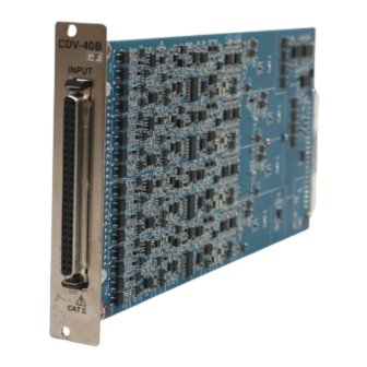
STRAIN/VOLTAGE MEASUREMENT CARD
Thank you for purchasing KYOWA's product CDV-40A/CDV-40A-F and
CDV-40B/CDV-40B-F STRAIN/VOLTAGE MEASUREMENT CARD for
EDX-2000A/EDX-100A.
Read this Instruction Manual carefully in order to make full use of the high
performance capabilities of the product.
Do not use the product in methods other than described in this Manual.
This product is a copyrighted work of KYOWA ELECTRONIC INSTRUMENTS CO., LTD. All rights
reserved.
Copying or reproduction of this product, whether in part or whole, is strictly prohibited without permission.
The contents of this Manual are subject to change without prior notice.
For EDX-2000A/EDX-100A
CDV-40B/CDV-40B-F
CDV-40A/CDV-40A-F
I
NSTRUCTION MANUAL
IM-A-604E January 2024
Advertisement
Table of Contents

Related Manuals for KYOWA CDV-40B


Summary of Contents for KYOWA CDV-40B
- Page 1 Do not use the product in methods other than described in this Manual. This product is a copyrighted work of KYOWA ELECTRONIC INSTRUMENTS CO., LTD. All rights reserved. Copying or reproduction of this product, whether in part or whole, is strictly prohibited without permission.
-
Page 3: Table Of Contents
CONTENTS STANDARD ACCESSORIES ............................1 SAFETY PRECAUTIONS ............................. 2 PRIOR TO USE......................................2 SAFETY SYMBOLS ..................................... 2 NOTATIONS USED IN THE INSTRUCTION MANUAL ..................3 1. PRODUCT OUTLINE ..............................4 1-1 OUTLINE OF CDV-40A/B ..................................4 1-2 PRECAUTIONS FOR USING THE CDV-40A/B ..........................4 1-3 OUTLINE OF CDV-40A/B-F (CDV-40A/B WITH ANTI-ALIASING FILTER) ................. -
Page 5: Standard Accessories
This Instruction Manual describes details of CDV-40A/CDV-40B/CDV-40A-F/CDV-40B-F Strain/Voltage Measurement Card for EDX-2000A/EDX-100A (hereinafter referred to as the CDV card). Difference between cards with or without ‘-F’ is described in the following. Model Name Anti-aliasing Filter Function CDV-40A/B Without CDV-40A/B-F With STANDARD ACCESSORIES The following accessories are packed with the CDV card. -
Page 6: Safety Precautions
PRIOR TO USE For safe use of the CDV-40A/B-F, do not forget to read the “Safety Precautions” prior to use. Kyowa Electronic Instruments Co., Ltd. assumes no liability for any damages resulting from user’s failure to comply with the safety precautions. -
Page 7: Notations Used In The Instruction Manual
NOTATIONS USED IN THE INSTRUCTION MANUAL Informational Notes Certain notations are used as necessary to attract users attention to information that requires special care when handing the CDV card, and to information provided for reference purposes. Examples of Notations NOTE Essential precautions required when handling the CDV card. -
Page 8: Product Outline
1. PRODUCT OUTLINE 1-1 OUTLINE OF CDV-40A/B • CDV card is a conditioner card for strain gages, strain gage transducers, and voltage output sensors. • Measurement of up to 8 CHs per CDV card is available • The CDV card is capable of reading TEDS (Transducer Electronic Data Sheet) built-in sensor information items. -
Page 9: Outline Of Cdv-40A/B-F (Cdv-40A/B With Anti-Aliasing Filter)
1-3 OUTLINE OF CDV-40A/B-F (CDV-40A/B WITH ANTI-ALIASING FILTER) • The CDV-40A-F card is a CDV-40A/B conditioner card mounted with anti-aliasing filter function. The anti-aliasing filter function is designed to prevent A/D converter from aliasing. • The anti-aliasing filter function of the CDV card is composed of 8th order Butterworth and attenuation obtained by entering 1/2 of sampling frequency is -48 dB ±5 dB. -
Page 10: Parts Names And Functions
1-5 PARTS NAMES AND FUNCTIONS Input connector Input connector for 8 CHs When connecting sensors, use dedicated input cables. Provided with the following dedicated input cables. CDV-40B List of Input Cables Product Model Cable Length Heat-shrinkable Product Model Cable Length... -
Page 11: Installing To Edx-2000A
“Card Type,” it is required to update the Slot No. Card Type EDX-2000A hardware. At this time, contact CDV-40B KYOWA or our representative for updating the CDV-40B EDX-2000A hardware. NOTE • When installing the CDV card into the EDX-2000A, do not touch any component parts of the CDV card. -
Page 12: Connecting Sensors
3. CONNECTING SENSORS The CDV card is capable of measuring strain and voltage. This section explains how to connect sensors to the CDV card from input cables. 3-1 WHEN USING STRAIN GAGE OR STRAIN GAGE TRANSDUCER To connect, hold this portion When measuring the output of the strain and push it in until it locks. -
Page 13: When Applying Voltage
3-2 WHEN APPLYING VOLTAGE End of input cable BNC cable Input conversion adapter: FV-1A +Bridge excitation voltage -Input -Bridge excitation voltage +Input ACOM ID signal+ Input conversion adapter: FV-1A (Optional) ACOM and FG are common potentials. When measuring the voltage, connect the FV-1A input conversion adapter (optional) to a quick mating connector using the BNC connector. -
Page 14: Centralized Connector Pin Assignment
4. CENTRALIZED CONNECTOR PIN ASSIGNMENT This section describes pin assignment of the centralized connector pins. Pin No. Name Pin No. Name Pin 1 Pin 26 Pin 50 Pin 25 Model: DN-50S Manufacturer: HIROSE Shield Shield... -
Page 15: How To Set Cdv-40A/B
5. HOW TO SET CDV-40A/B If the CDV card is already installed in the EDX-2000A, settings of all the required conditions are conducted from the EDX-2000A. EDX-2000A Initial Window 2) Setting Conditions ↓ 1) CH Condition Items 1) Meas CH 2) Mode 3) Range 4) HPF... - Page 16 EDX-2000A, CDV-40A or CDV-40B appears on the initial window. (The window at the right shows that CDV-40B is installed in the 1st to 4th slots.) Here, set the cursor to the item 2) Condition and press the ENTER key.
- Page 17 Mode Select the item 2) Mode on the CH Condition window to display the right window. Set the cursor to either Strain or Voltage for every CH and press the ENTER key. Range Select the item 3) Range on the CH Condition window to display the right window.
- Page 18 BAL ON/OFF Select the item 6) BAL ON/OFF on the CH Condition window to display the right window. BAL ON/OFF is selected to set whether or not to conduct strain bridge initial adjustment (balance) of the measuring CH. Set the cursor to “ON” or “OFF” for every CH and press the ENTER key. Here, a CH set to balance “ON”...
- Page 19 NOTE SHUNT Insert a fixed resistance between ‘+BV’ and ‘+IN’ of the strain gage bridge and output a value obtained by adding the bridge output value at that time to the current output value. Irrespective or measuring range or CAL output range, it is determined by the bridge resistance of the strain sensor.
-
Page 20: How To Set Anti-Aliasing Filter (Only For Cdv-40A/B-F)
1) CH Condition Initial window Select “AUTO” Figure 1. Operational Flow for Setting Anti-aliasing Filter 1) After starting up the EDX-2000A, check whether or not the CDV-40A-F or CDV-40B-F is installed in the EDX-2000A. (See Figure 2.) The left window shows that... - Page 21 3) Select 1) CH Condition on the Condition Window to display the following window as shown in Figure 4. Figure 4. CH Condition Window 4) Select 5) Low Pass Filter on the CH Condition window to display the following window in Figure 5. Figure 5.
-
Page 22: Precautions For Setting Anti-Aliasing Filter
7. PRECAUTIONS FOR SETTING ANTI-ALIASING FILTER • When AUTO is not indicated on the Low Pass Filter menu items Allowable sampling frequency range of the anti-aliasing filter is 100 Hz or more. If the sampling frequency is set to less than 100 Hz as shown in the Figure 6, AUTO does not appear on the Low Pass Filter menu items. When sampling frequency is set AUTO is not... - Page 23 • When it is required to set sampling frequency to 100 Hz or less When setting the sampling frequency to 100 Hz or less, in some cases, it is not available to set the sampling frequency to the required 100 Hz. If AUTO is set to any CH on the Low Pass filter menu items, sampling frequencies of less than 100 Hz are not displayed.
-
Page 24: Outside Drawing
8. OUTSIDE DRAWING CDV-40A/B CDV-40A/B-F... -
Page 25: Specifications
2 steps: 0.2 Hz and 1 Hz High pass filter (DC cut)) Attenuation characteristics -6 dB/oct AD converter resolution 16 bits Additional function Read TEDS built-in sensor information Directive 2014/30/EU (EMC) Compliance(*2) Directive 2011/65/EU,(EU)2015/863(10 restricted substances) (RoHS) (*1) Only for CDV-40A/B-F (*2) Only for CDV-40B,CDV-40B-F...
Need help?
Do you have a question about the CDV-40B and is the answer not in the manual?
Questions and answers