Table of Contents
Advertisement
Quick Links
STRAIN/VOLTAGE/ACCELERATION MEASUREMENT CARD
Generally, company names and trade names described in this Instruction Manual are trademarks or registered
trademarks of the companies.
This Instruction Manual may not be copied or reproduced, in whole or part, without consent of KYOWA.
Copyright © KYOWA ELECTRONIC INSTRUMENTS CO., LTD. All rights reserved.
The contents of the Instruction Manual are subjected to change without prior notice.
Kyowa Electronic Instruments Co., Ltd. assumes no liability for any damage resulting from the use of this
product.
INSTRUCTION MANUAL
Thank you for purchasing KYOWA's product CVM-41A
Strain/Voltage/Acceleration Measurement Card for EDX-100A
Universal Recorders/EDX-200A Universal Recorders
/EDX-3000A Memory Recorder/Analyzers.
Read this Instruction Manual carefully in order to make full use of
the high performance capabilities of the product.
Do not use the product in methods other than described in this
Manual.
IM-A-1037C February 2023
CVM-41A
Advertisement
Table of Contents

Subscribe to Our Youtube Channel
Related Manuals for KYOWA CVM-41A


Summary of Contents for KYOWA CVM-41A
- Page 1 Generally, company names and trade names described in this Instruction Manual are trademarks or registered trademarks of the companies. This Instruction Manual may not be copied or reproduced, in whole or part, without consent of KYOWA. Copyright © KYOWA ELECTRONIC INSTRUMENTS CO., LTD. All rights reserved.
-
Page 2: Table Of Contents
SAFETY PRECAUTIONS (Do not forget to read the safety precautions prior to use.) ........... 2 LIMITED LIFE PARTS AND PREVENTIVE MAINTENANCE ................3 CVM-41A REPLACEMENT BEFORE THE END OF SERVICE LIFE ..............3 NOTATIONS USED IN THE INSTRUCTION MANUAL ..................4 CE MARKING ................................ -
Page 3: Standard Accessories
STANDARD ACCESSORIES The following accessories are packed with the CVM-41A Strain/Voltage/Acceleration Measurement Card (hereinafter referred to as the CVM-41A). When unpacking, check the contents to ensure that all accessories are enclosed. Term and Conditions of Product Warranty READ IN THE BIGGINING Cross-recessed binding head machine screw M3 ×... -
Page 4: Safety Precautions (Do Not Forget To Read The Safety Precautions Prior To Use.)
● Lay input cables at proper intervals with a certain play so that they may not receive any unreasonable force. Failure to do so will pose the risk of erroneous data, disconnection and connector failure. ● Do not disassemble or remodel the CVM-41A. Failure to do so will pose the risk of electric shock and system failure. -
Page 5: Limited Life Parts And Preventive Maintenance
Preventive maintenance and replacement parts are a cost-effective way of keeping the performance and extending the service life of the CVM-41A. Regardless of the replacement parts, the CVM-41A itself gradually deteriorates with age. Before the expected service life is reached, consider replacing the CVM-41A with a new one or the latest series as preventive maintenance. -
Page 6: Notations Used In The Instruction Manual
CE MARKING NOTE By affixing the CE marking, KYOWA confirms that the CVM-41A, satisfying the following conditions, complies with requirements of the EU Directives by assessing the conformity of the requirements established by the EU Directives. (For the complying requirements established by the EU Directives, see "4 SPECIFICATIONS".) -
Page 7: Outline Of The Product
1. OUTLINE OF THE PRODUCT 1.1 Outline of CVM-41A ・ The CVM-41A is a conditioner card for a strain gage, strain gage transducer, voltage, and piezoelectric accelerometer (built-in amplifier). The CVM-41A is available in all of EDX series except the EDX-10A and EDX-2000A/B. -
Page 8: Pin Assignment And Connection Of Input Connector
1.3 Pin Assignment and Connection of Input Connector 1) Input connector [Pin assignment] Pin No.25 Pin No.50 Pin No.1 Pin No.26 Pin No. Connection Pin No. Connection CH1 A CH1 C CH1 F CH1 E,G CH1 B CH1 D CH2 A CH2 C CH2 F CH2 E,G... - Page 9 To disconnect, unfasten the two screws. Push in the release buttons on the both sides, hold the plug case and pull it. MEMO ● CVM input cable is available in the common CVM-40A and CVM-41A. NOTE ● When you disconnect a cable, do not pull on the cable itself.
- Page 10 2) Monitor output connector [Pin assignment] Pin No. Signal Name Pin No. 1 Pin No.6 CH1 monitor output CH2 monitor output CH3 monitor output CH4 monitor output Pin No.5 Pin No.9 CH5 monitor output CH6 monitor output CH7 monitor output CH8 monitor output [Connection Method] Centralized output cable: U-62 (optional)
-
Page 11: Installation Of Cvm-41A
● Always turn OFF the EDX-100A/200A/3000A before installing/removing the CVM-41A. Or, damage on the CVM-41A or EDX-100A/200A/3000A may result in. ● When installing or removing the CVM-41A in/from the EDX-100A/EDX-200A/EDX-3000A, do not touch any component parts of the CVM-41A. Or, system failure or damage may result in. -
Page 12: Connecting Sensors
NOTE ● The F terminal (channel input) of the CVM-41A is intended for sensor ID signals (TEDS). Connecting any other signal to this terminal may prevent the EDX-100A/200A/3000A from recognizing all conditioners installed in the system. -
Page 13: When Applying An Input Voltage
● Do not apply any voltage beyond the specified input voltage range. The specified input voltage range of the CVM-41A is ±50 V. Failure to do so will pose the risk of electric shock, deteriorated performance and system failure. ●... -
Page 14: When Using A Piezoelectric Accelerometer (Built-In Amplifier)
(optional) to a CVM input cable U-121 to U-123 (optional) as shown in the following figure. NOTE ● Compatible sensor for the CVM-41A is a piezoelectric accelerometer (built-in amplifier). No measurement is allowed if an electric charge output type piezoelectric accelerometer is directly connected. - Page 15 Although the time required until the output voltage becomes stable varies according to sensors in use or CVM-41A measuring range, the output voltage becomes stable in approximately 20 to 40 seconds. Wait for a while until it becomes stable before starting the measurement.
-
Page 16: Setting Channel Conditions
3 SETTING CHANNEL CONDITIONS For the EDX-100A/200A, use the DCS-100A in your PC for settings. For the EDX-3000A, use the EDX-3000A itself or DCS-100A in your PC for settings. For details, refer to "DCS-100A Instruction Manual for EDX-100A/200A/3000A" and "EDX-3000A Instruction Manual for Hardware."... -
Page 17: Details Of Channel Conditions
Or, damage on the CVM-41A or sensors may result in. ● When install for EDX-100A, number of channels that can be set to "Strain (10 V)" or "Voltage (10 V)" mode, will be installed number of CVM-41A × 3 channels or less. 3) Range Select an appropriate measuring range according to the rated output of the sensor, estimated maximum output, etc. - Page 18 ・ The smaller the measuring range is, the higher becomes the gain of the CVM-41A. Therefore, the noise tends to become larger. ● Set the “Range” to OFF. The excitation voltage and sensor power supply are automatically set to OFF (0 V).
- Page 19 6) Balance Select the auto-balancing ON/OFF/NONE (or zero-suppress ON/OFF/NONE) for each channel. When the strain mode and Balance ON (or OFF) are selected, the input unbalance is (not) balanced utilizing the analog circuit. When the strain mode and Balance NONE are selected, the auto-balancing function is invalid.
- Page 20 NOTE When SHUNT is selected Connect a fixed resistance between the [+BV] and [+IN] of the strain gage bridge. A certain value based on the fixed resistance appears. The output value is determined by the bridge resistance of the strain gage bridge irrespective of the Range and CAL range.
-
Page 21: Specifications
When using the voltage conversation adapter FV-1A (at unbalanced input), within 1M ± 10%. (*6) When installed in EDX-100A, number of channels that can be set to bridge excitation BV10V or sensor power supply 10VDC (±5V) mode, will be installed number of CVM-41A × 3 channels or less. - 19 -... - Page 22 Acceleration Item Strain measurement Voltage measurement measurement (Piezoelectric) BV2V: 2k, 5k, 10k, 20k, 50k, 100k, 200k, 500k m/m 100, 200, 500, 1000, 2000, Measurement range BV5V: 2k, 5k, 10k, 20k, 1, 2, 5, 10, 20, 50 V 5000 mV 50k, 100k, 200k m/m BV10V: 2k, 5k, 10k, 20k, 50k, 100k m/m Range accuracy...
-
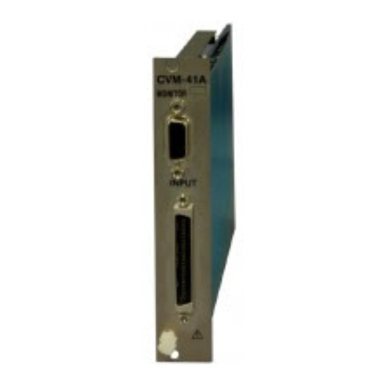
Page 23: Outside Drawings
4.2. Outside Drawings - 21 -... -
Page 24: Optional Accessories
5 OPTIONAL ACCESSORIES CVM input cable: U-121, U-122, U-123 The input connector is connected. For how to connect the centralized input cable, see “1-3 PIN ASSIGNMENT AND CONNECTION OF CONNECTORS.” U-121…Cable length: Approx. 0.5 m U-122…Cable length: Approx. 1.0 m U-123…Cable length: Approx. - Page 25 Cable length: Approx. 1.0 m CVM concentrated input cable: N-121 For connecting the voltage input box VI-8A, small-sized bridge box for 1-gage system DBS-120A-8/-350A-8, or one-touch lock type bridge box DB-120V-8/-350V-8 into the CVM-40A, CVM-41A. Cable length: Approx. 1.5 m Voltage Input Box: VI-8A(-T) Capable of gathering signals from 8 BNC connectors into one for measuring voltage and piezoelectric accelerometers (built-in amplifier).
- Page 26 Small-sized bridge box for 1-gage system: DBS-120A-8(T), DBS-350A-8(T) Small-sized 8-channel bridge box for strain measurements For the 1-gage 2-wire system and 1-gage 3-wire system. DBS-120A-8…For the gage resistance of 120 ohm DBS-120A-8T…For the gage resistance of 120 ohm with the mounting board DBS-350A-8…For the gage resistance of 350 ohm DBS-350A-8T…For the gage resistance of 350 ohm with the mounting board DBS-120A-8/350A-8...
-
Page 27: Appendix
When inputting the same strain signal or the same voltage signal into the CVM-41A and CDV-40B/A at the same time, time lag occurs between the data of the CVM-41A and that of the CDV-40B/A. Time lag occurs due to the difference of the frequency response, low-pass filter circuit, and A/D converter included in every conditioner card. - Page 28 (2) For the Acc. mode Table 6-2 The low-pass filter and time lag between the CVM-41A and CCA-40A (-F) Low-pass filter of the Frequency response Sampling Frequency Time lag of the CVM-41A CVM-41A, CCA-40A of the CVM-41A (Hz) [μsec] (-F) [Hz]...
-
Page 29: Time Lag Between Cvm-41A And Cvm-40A
6.2 Time Lag between CVM-41A and CVM-40A Between CVM-41A and CVM-40A, some of the time lag occurs in the analog output by the difference of the filter characteristics. When recording in sampling frequency [1000 / Time Lag (msec)] (Hz) or more, the number of samples corresponding to the time lag, it can be calculated by the [Time lag (msec) / 1000 ×...
Need help?
Do you have a question about the CVM-41A and is the answer not in the manual?
Questions and answers