
Subscribe to Our Youtube Channel
Related Manuals for KYOWA WDS-190AS1E


Summary of Contents for KYOWA WDS-190AS1E
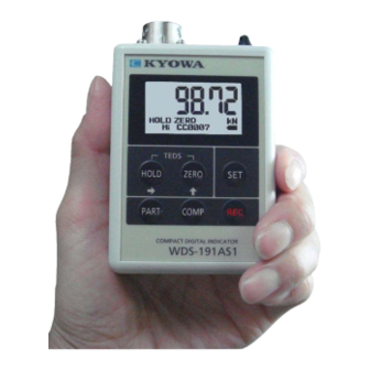
- Page 1 PR-T-370-011 Sept, 2020 INSTRUCTION MANUAL WDS-190AS1E WDS-191AS1E COMPACT DIGITAL INDICATOR...
- Page 3 Generally, company names and trade names described in this Instruction Manual are trademarks or registered trademarks of the companies. This Instruction Manual may not be copied or reproduced, in whole or part, without consent of KYOWA. Copyright © Kyowa Electronic Instruments Co., Ltd. All rights reserved.
-
Page 4: Table Of Contents
CONTENTS SAFETY PRECAUTIONS ..........................1 1 OUTLINE ..............................2 2 FEATURES ..............................2 3 CONFIGURATION ............................2 4 CONTROLS AND INDICATORS ........................3 5 CONNECTING TRANSDUCERS ......................... 4 6 INSTALLING AND REMOVING BATTERIES ..................... 4 7 OPERATIONS AND FUNCTIONS ........................ 5 7-1 [POWER] SWITCH .......................... -
Page 5: Safety Precautions
PRIOR TO USE For safe use of the product, do not forget to read the "Safety Precautions" prior to use. Kyowa Electronic Instruments Co., Ltd. assumes no liability for any damage resulting from the user's failure to comply with the safety precautions. -
Page 6: Outline
The WDS-191AS1E records data and saves CSV files in text format. To read the CSV files, use commercially available software (Microsoft Excel). The WDS-190AS1E/WDS-191AS1E is able to be used in wide application such as for checking transducers and simplified measurement. -
Page 7: Controls And Indicators
4 CONTROLS AND INDICATORS ① Input connector 2 Connects a strain gage transducer. ② [POWER] switch POWER: Turns ON/OFF the power. 1 Turns ON/OFF the backlight. STRAIN: STRAIN mode MEAS: MEAS mode Converts raw outputs of strain gage transducers into physical quantities. ③... -
Page 8: Connecting Transducers
Check the recommended excitation voltage of the transducer is 2 V or more. 6 INSTALLING AND REMOVING BATTERIES Push down and open the battery case cap on the WDS-190AS1E/WDS-191AS1E rear. Locate and correctly insert accessory or commercially available size AA batteries in the battery case center band mentioned on the battery case. -
Page 9: Operations And Functions
7 OPERATIONS AND FUNCTIONS The WDS-190AS1E/WDS-191AS1E has 2 modes; STRAIN mode and MEAS mode. The "STRAIN mode" measures raw outputs of strain gage transducers. The "MEAS mode" converts raw outputs of strain gage transducers into physical quantities. Tips!! Basically the WDS-190AS1E/WDS-191AS1E operates by clicking. - Page 10 To use the KEY LOCK, select ON on the F-15 “KEY LOCK.” For details, see “9 FUNCTION SELECTING MODES.” KEY LOCK: ON When the KEY LOCK is ON, the WDS-190AS1E/WDS-191AS1E starts with the locked status and the key mark appears.
-
Page 11: Orig Unit (F-1)
7-2 ORIG UNIT (F-1) The WDS-190AS1E/WDS-191AS1E indicates outputs of strain gage transducers in “με” or “mV/V”. (”με” = “10 strain” = “μm/m”) The WDS-190AS1E/WDS-191AS1E uses the units for STRAIN mode and ENROLMNT ADJ (F-3). Before operating the WDS-190AS1E/WDS-191AS1E, select “με” or “mV/V”. -
Page 12: Meas Mode
Click the ZERO key with no load applied to the transducer. The WDS-190AS1E/WDS-191AS1E saves the “zero” value. NOTE: Before calibrations, be sure to execute the digital zero function. Since the “zero” value is equivalent to the calibration value, the WDS-190AS1E/WDS-191AS1E saves the “zero” value in the internal memory. -
Page 13: Load Adj (F-2)
7-4-3 LOAD ADJ (F-2) The F-2 calibrates data by applying the known load actually. Apply load: Apply the known load to the transducer. FUNCTION SELECTING mode: Press and hold the SET key. The “F-1” appears. LOAD ADJ: Click the key. The “F-2”... -
Page 14: Enrolmnt Adj (F-3)
Make sure the coefficients are within 0.009 to 110. Or, “CcErr” appears and “EA” appears on the bottom left. If the coefficients are not within 0.009 to 110, the WDS-190AS1E/WDS-191AS1E calculates the rated capacity (RC) by ignoring the decimal point and calculates the rated output (RO) in “με.”... -
Page 15: Meas Unit (F-12)
7-5 MEAS UNIT (F-12) This section describes how to select units for the MEAS mode. You are able to create custom units. STRAIN με, μm/m, μV/V, mV/V FORCE MASS PRESSUR hPa, kPa, TORQUE mN・m, N・m, kN・m, MN・m DSPLACE μm, ACCELER Gal, No unit CUSTOM... -
Page 16: Smooth (F-4)
7-6 SMOOTH (F-4) The F-4 function decreases the variation of indicating values to read data easily. 1) AVERAGE: Select the number of moving average data. The sampling rate is 50 times/sec. Suppose the sampling rate is 64 times, the AVERAGE is 1.28 sec. 2) MIN-VAL: Increases/decreases the indicating value by steps. -
Page 17: Low Power (F-5)
7-7 LOW POWER (F-5) The F-5 has PWR OFF and BKL OFF. The F-5 prevents unnecessary consumption of batteries from turning ON the [POWER] switch and backlight for too long. 1) PWR OFF: Prevents unnecessary consumption of batteries from turning ON the [POWER] switch for too long. -
Page 18: Peak Hold Function
Make sure no load is applied to transducers. Click the HOLD key and ZERO key at the same time (for approx. 1 second). The WDS-190AS1E/WDS-191AS1E executes the sensitivity registration automatically. -
Page 19: Teds Func (F-10)
The value, obtained in ② ZERO AT READ, is equivalent to the “zero” value, obtained in “7-4-2 Preparation for calibration.” The WDS-190AS1E/WDS-191AS1E uses the value, obtained in ② ZERO AT READ, as standards. NOTE 2 Suppose the RATED OUTPUT is DIS and RATED CAPACITY is DIS. -
Page 20: Enrol By File
7-10-4 ENROL BY FILE Reads the K.S/N from the transducer TEDS data, find the same K.S/N file in the WDS-190AS1E/WDS- 191AS1E calibration files, and registers the rated outputs, rated capacities, decimal point positions, units, “zero” value, and smooth items automatically. - Page 21 REG: Registers the setting contents. (Available when the file has no data.) Click the SET key. The WDS-190AS1E/WDS-191AS1E executes the target item and goes to the calibration file selection window. To register/delete data, select a calibration file again. Click the ZERO key.
-
Page 22: Comparator Functions And Recording Functions (Wds-191As1E Only)
8 COMPARATOR FUNCTIONS AND RECORDING FUNCTIONS (WDS-191AS1E ONLY) The WDS-191AS1E has a recording function that records the data, measured with the MEAS mode, in the internal memory and comparator function. The WDS-191AS1E saves the recorded data in an internal memory as CSV files. 8-1 COMPARATOR FUNCTIONS The WDS-191AS1E has one HI comparator. -
Page 23: Clock Adj (F-6)
8-3 CLOCK ADJ (F-6) This section describes how to adjust date and time, saved in the data. FUNCTION SELECTING mode: Click the SET key. The “F-1” appears. Adjust the time: Click the key. The “F-6” appears. Click the SET key. The highest-order digit of the current time blinks. -
Page 24: Recording Functions
8-4 RECORDING FUNCTIONS As you click the REC key, the WDS-191AS1E records measured values in the internal memory. Data is comma-delimited CSV files. To read the CSV files, use commercially available software (Microsoft Excel). 1) To create files The internal memory has no file. Click the REC key. -
Page 25: Retrieving Functions
3) To check/delete data This section describes how to check/delete the latest recorded data. Check data. Click the SET key and REC key at the same time (for approx. 1 second). The latest recorded data appears. RECORD MAINTE Year/month/day hour/minute/second Part name Count value (counts up) Measured value... -
Page 26: Function Selecting Modes
9 FUNCTION SELECTING MODES Press and hold the SET key (for approx. 2 seconds) while measuring data. The FUNCTION SELECTING mode “F-1” appears. To change the FUNCTION SELECTING mode, click the key. To check the setting contents, click the SET key. The “F-**”... - Page 27 Mode Key operations Functional description The pre-set value blinks. LOW POWER PWR OFF The PWR OFF prevents (Initial value Select the target from 00 to 99 min by using the unnecessary consumption of PWR OFF: 0 MIN key and key. Click the SET key. batteries from turning ON the BKL OFF: 10 SEC) [POWER] switch for too long.
- Page 28 Mode Key operations Functional description F-11 The “F-11” and following items appear The F-11 saves the K.S/N, FILE MAINTE alternately. CAPACITY, rated output, decimal point position, unit, FILE No.: “zero” value, and smooth CAPACITY: ***** items in files (file No. 1 to K.S/N: ********* 32).
- Page 29 (for approx. 3 seconds). NOTE To confirm the FUNCTION SELECTING mode, be sure to click the ZERO key and go to the measuring window. The WDS-190AS1E/WDS-191AS1E does not confirm the FUNCTION SELECTING mode by clicking the SET key.
-
Page 30: Error Code
10 ERROR CODE Error codes appear on the bottom left. When an error appears, re-set settings or turn IdErr OFF and ON the power. Error codes Error codes on the bottom left EW: EEPROM writing error EA: Calibration value setting error EU: User setting area SUM error ER: RTC error or require initialization EF: Fact setting area SUM error... -
Page 31: Specifications
11 SPECIFICATIONS Model WDS-190AS1E WDS-191AS1E (including the comparator function and recording function) Applicable sensor Strain gage transducer (input terminal resistance: 60 ohm to 1000 ohm) Bridge excitation 2 VDC (constant) Measuring range ±5.0000 mV/V (±10000 µm/m) Including the zero adjustment range... -
Page 32: Outside Drawing
Dimensions 66.5 (W) × 92 (H) × 28 (D) mm (Excluding protrusions) Weight Approx. 110 g (excluding batteries) EMC Directive EN61326-1(IEC61000-4-2, IEC61000-4-3 only RoHS Directive EN50581:2012 Options Soft case WDS-500-CASE (With shoulder strap storing AA size battery × 2 and input cable U-16 × 1) Input cable U-16 0.5 m, alligator clip at one end 12 OUTSIDE DRAWING...
Need help?
Do you have a question about the WDS-190AS1E and is the answer not in the manual?
Questions and answers