Table of Contents
Advertisement
Quick Links
Generally, company names and trade names described in this Instruction Manual are trademarks or registered
trademarks of the companies.
This Instruction Manual may not be copied or reproduced, in whole or part, without consent of KYOWA.
Copyright © Kyowa Electronic Instruments Co., Ltd. All rights reserved.
The contents of the Instruction Manual and specifications of the software are subject to change without prior
notice.
INSTRUCTION MANUAL
ONE-TOUCH TYPE BRIDGE BOX
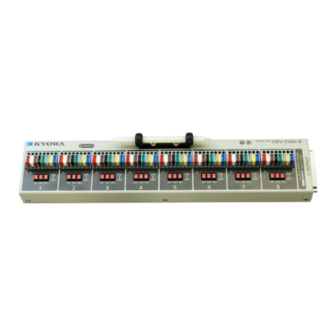
Thank you for purchasing KYOWA's product DBV-120A-8/DBV-350A-8
One-touch Type Bridge Box.
Read this Instruction Manual carefully in order to make full use of the high
performance capabilities of the product.
Do not use the product in methods other than described in this Manual.
IM-A-1100 February 2016
DBV-120A-8
DBV-350A-8
Advertisement
Table of Contents

Related Manuals for KYOWA DBV-120A-8


Summary of Contents for KYOWA DBV-120A-8
- Page 1 Generally, company names and trade names described in this Instruction Manual are trademarks or registered trademarks of the companies. This Instruction Manual may not be copied or reproduced, in whole or part, without consent of KYOWA. Copyright © Kyowa Electronic Instruments Co., Ltd. All rights reserved.
-
Page 3: Table Of Contents
CONTENTS STANDARD ACCESSORIES........................1 OPTIONS................................. 1 SAFETY PRECAUTIONS..........................2 PRIOR TO USE .............................. 2 SAFETY SYMBOLS ............................2 NOTATIONS USED IN THE INSTRUCTION MANUAL................ 4 1. PRODUCT OUTLINE ..........................5 1-1 PRODUCT OUTLINE ......................... 5 1-2 FEATURES ............................5 2. PARTS AND FUNCTIONS........................6 3. -
Page 4: Standard Accessories
This Instruction Manual describes One-touch Type Bridge Box DBV-120A-8(C) and DBV-350A-8(C) (hereinafter referred to as the Bridge Box). STANDARD ACCESSORIES The Bridge Box comes with the following standard accessories. After unpacking, check to be sure that they are included. Small Screwdriver ............. -
Page 5: Safety Precautions
This Instruction Manual describes detailed instructions for operating the Bridge Box. For safe use of the Bridge Box, do not forget to read the “Safety Precautions” prior to use. Kyowa Electronic Instruments Co., Ltd. assumes no liability for any damages resulting from user’s failure to comply with the safety precautions. - Page 6 CAUTION ● Use the Bridge Box in the specified operating temperature range 0 to 40ºC. Use at temperatures exceeding the specified range may lower the performance and cause trouble. If use under direct sunlight or in a cold place is inevitable, prepare a sunscreen or take proper measures to keep it warm.
-
Page 7: Notations Used In The Instruction Manual
NOTATIONS USED IN THE INSTRUCTION MANUAL Informational Notes Certain notations are used as necessary to attract your attention to information that requires special care when handing the Bridge Box, and to information provided for reference purposes. Examples of Notations NOTE Essential precautions when handling the Bridge Box. -
Page 8: Product Outline
1. PRODUCT OUTLINE 1-1 PRODUCT OUTLINE The Bridge Box is 8-channel type bridge box for strain gage measurement. Set a gage mode with gage mode switch on the upper face of the Bridge Box and connect a strain gage to the one-touch type terminal board. Connect the dedicated cable to an input of the strain meter for the strain gage measurement. -
Page 9: Parts And Functions
2. PARTS AND FUNCTIONS 1 Terminal Board for Connecting Strain Gages One-touch type terminal board (1-CH) for connecting the lead wire of the strain gage. See “3-2 CONNECTING STRAIN GAGE” for the connection. MEMO ● Applicable lead wire Solid wire: φ0.4 mm to φ1.2 mm (UL AWG16 to 26) Stranded wire: 0.2 mm to 0.75 mm (UL AWG20 to 24) - Page 10 NOTE ● Grounding the GND terminal Be sure to ground the GND terminal. Or, it may cause an electric shock hazard, lower the performance, and cause trouble. MEMO ● For the GND terminal Connect the GND terminal and E (S) terminal (gray) when noisy. The noise may be reduced.
-
Page 11: Connecting Form
3. CONNECTING FORM 3-1 SETTING FORM OF GAGE MODE The gage mode has 5 types; 1/4 BRIDGE (2WIRE) system, 1/4 BRIDGE (3WIRE) system, 1/2 BRIDGE system, 2GAGE (OPPOSITE) system and FULL BRIDGE system. The connecting form of the strain gage and setting of gage mode switch (SW1 to SW3) for every gage system are described as follows. -
Page 12: Connecting Strain Gage
3-2 CONNECTING STRAIN GAGE 1) Push the button with the accessory small screwdriver. NOTE ● Press the following position. Be sure to press the above position with the accessory small screwdriver. ● For connection, always use the accessory small screwdriver or an object with a fine head. - Page 13 3) Release the lock button with the lead wire held in position. 4) Gently pull the lead wire to check if it is securely inserted. MEMO For connection, always use the accessory small screwdriver or an object with a fine head.
-
Page 14: Connecting Strain Meter
3-3 CONNECTING STRAIN METER Use the following connector to connect the strain meter. For the strain meter with NDIS connector. N-104 For the strain meter CDV-40B/A. N-105 Each cable length is 1.5 m. Since the N-104 or N-105 connector has a lock Release buttons function to prevent itself from falling off, the N-104 or N-105 connector is locked just by inserting it. - Page 15 MEMO ● About the connection part between the N-104 or N-105 connector and cable. The connector having wide range of connection movement between the connector and cable is used for the cable. Therefore, the cable moves up, down, left, or right direction at the connection part. This is used to release the extra force that is transmitted to the fitting portion of the connector from the cable.
-
Page 16: Select Led
4. SELECT LED 4-1 OUTLINE When using multiple Bridge Boxes, by lightening the SELECT LEDs, you can identify which Bridge Boxes are connected to the target CDV-40B/A. Connect the Bridge Box to the CDV-40B/A with the N-105 cable for using the SELECT LED. 4-2 WITH THE EDX-3000A/B Click the Environment icon and select the Configuration tab on the EDX-3000A/B. -
Page 17: Specifications
5. SPECIFICATIONS Model Name DBV-120A-8 (For gage resistance 120 ohm, accessory cable N-104). DBV-350A-8 (For gage resistance 350 ohm, accessory cable N-104). DBV-120A-8C (For gage resistance 120 ohm, accessory cable N-105). DBV-350A-8C (For gage resistance 350 ohm, accessory cable N-105). -
Page 18: For Screw Holes On Bottom Panel
6. FOR SCREW HOLES ON BOTTOM PANEL Four holes for M3 screws are arranged on the bottom panel of the Bridge Box. The screw holes are for fixing the Bridge Box with the fixing screws. Depth of the screw holes are 6 mm. In addition, put the accessory rubber feet (4) when not using the holes. -
Page 19: For Outside Drawing And Dimensions Of Bridge Box Mounting Board
7. FOR OUTSIDE DRAWING AND DIMENSIONS OF BRIDGE BOX MOUNTING BOARD The following figure is an example of the bridge box mounting board using the screw holes on the bottom panel of the Bridge Box. Refer to the following figure. Use four flat countersunk screws M3 with length (board thickness (t) + 4 to 6 mm) for mounting the following mounting board to the Bridge Box. -
Page 20: Outside Drawing
8. OUTSIDE DRAWING DBV-120A-8 and DBV-350A-8 (Unit: mm) N-104 Cable 1.5m N-105 Cable 1.5m... - Page 24 Kyowa Electronic Instruments Co., Ltd. 3-5-1, Chofugaoka, Chofu, Tokyo 182-8520 Japan http://www.kyowa-ei.com/...
Need help?
Do you have a question about the DBV-120A-8 and is the answer not in the manual?
Questions and answers