Table of Contents
Advertisement
Thank you for purchasing KYOWA's product WDS-180A (Compact
Digital Indicator).
Read this Instruction Manual carefully in order to make full use of the
high performance capabilities of the product.
Do not use the product in methods other than described in this
Manual.
Copyright © KYOWA ELECTRONIC INSTRUMENTS CO., LTD. All rights reserved.
This Instruction Manual may not be copied or reproduced, in whole or part, without consent of
KYOWA.
The contents of the Instruction Manual are subjected to change without prior notice.
COMPACT
DIGITAL INDICATOR
WDS-180A
INSTRUCTION MANUAL
IM-A-682D March 2016
Advertisement
Table of Contents

Subscribe to Our Youtube Channel
Related Manuals for KYOWA WDS-180A


Summary of Contents for KYOWA WDS-180A
- Page 1 Do not use the product in methods other than described in this Manual. Copyright © KYOWA ELECTRONIC INSTRUMENTS CO., LTD. All rights reserved. This Instruction Manual may not be copied or reproduced, in whole or part, without consent of KYOWA.
- Page 2 - 1 -...
-
Page 3: Table Of Contents
CONTENTS SAFETY PRECAUTIONS ......................1 1. OUTLINE ............................ 3 2. FEATURE ........................... 3 3. CONFIGURATIONS ........................3 4. PARTS NAMES AND MAIN FUNCTIONS ................4 5. CONNECTING TRANSDUCER ....................5 6. INSTALLING AND REMOVING BATTERY................5 7. SETTING OPERATION AND FUNCTION................6 7-1 SWITCHING STRAIN UNIT (F-1) ..................... -
Page 4: Safety Precautions
This Manual describes detailed instructions for installing and setting up the WDS-180A Compact Digital Indicator (hereinafter referred to as the WDS-180A). For safe use of the WDS-180A, do not forget to read the ‘Safety Precautions’ prior to use. KYOWA ELECTRONIC INSTRUMENTS CO., LTD. assumes no liability for any damages resulting from user’s failure to comply with the safety precautions. - Page 5 OFF the power. Or, electric shock or fire hazard may result. Contact KYOWA or our representative for repair. 4) Do not put water or foreign matters into the WDS-180A. In case if any foreign matters are entered, immediately turn OFF the power. Or, electric shock or fire hazard may result.
-
Page 6: Outline
The WDS-180A is a compact and lightweight digital indicator specified for strain gage transducers. The WDS-180A is an indicator that not only displays physical quantity of the transducer but measures the initial value of the transducer in [μm/m] or [mV/V] and conducts automatic sensitivity registration when the Transducer Electronic Data Sheet (hereinafter referred to as the TEDS)-compatible transducer is connected. -
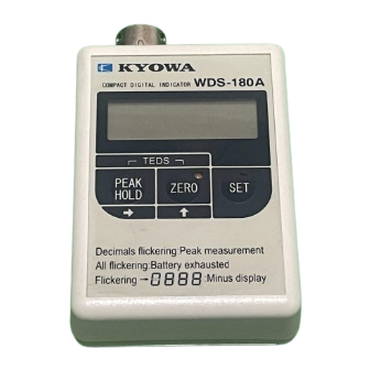
Page 7: Parts Names And Main Functions
:Minus display Flickering 1) Input Connector: ∙∙∙∙∙∙∙∙∙∙∙∙∙∙∙∙∙∙∙∙∙∙ Connects the strain gage transducer. 2) Power Switch: ∙∙∙∙∙∙∙∙∙∙∙∙∙∙∙∙∙∙∙∙∙∙∙∙∙∙ OFF: Turns the WDS-180A OFF. STRAIN: Strain Measuring Mode MEAS: Displays physical quantity converted data. 3) Indicator: ∙∙∙∙∙∙∙∙∙∙∙∙∙∙∙∙∙∙∙∙∙∙∙∙∙∙∙∙∙∙∙∙∙ Displays 4 digits numerical value. 4) → PEAK HOLD Key: ∙∙∙∙∙∙∙∙∙∙∙... -
Page 8: Connecting Transducer
(With 120 ohm transducer connected, when batteries are used with LED OFF at room temperature 25˚C) Manganese battery: 24 hours or more Alkaline battery: Approximately 100 hours • To remind you to turn the WDS-180A OFF, setting the ‘Auto-Power OFF (F-5)’ is recommended. The initial value is not set. - 5 -... -
Page 9: Setting Operation And Function
7. SETTING OPERATION AND FUNCTION The WDS-180A is provided with ‘STRAIN Mode (STRAIN)’ that measures the actual output of the strain gage transducer and ‘MEAS Mode (MEAS)’ that displays physical quantity by multiplying coefficient. 7-1 SWITCHING STRAIN UNIT (F-1) • The WDS-180A displays the output of the strain gage transducer in [μm/m] or [mV/V]. -
Page 10: Meas Mode
7-3 MEAS MODE Converts the output of the strain gage transducer to the physical quantity and displays the converted data. 7-3-1 Calibration Registers the conversion coefficient for displaying the transducer output in physical quantity. It is essential to conduct either the ‘Load CAL (Actual Load Calibration)’ or ‘Sensitivity CAL (Sensitivity Registration Calibration).’... -
Page 11: Min Digit (Minimum Digit Scale F-4)
7-3-5 Min Digit (Minimum Digit Scale F-4) Makes the indication stable and offers easy-to-read display. The Min digit (Minimum digit scale) of the indicated value appears in every 1, 2, or 5 step. • Function: Press the SET key to display [F-1]. •... -
Page 12: Teds Function
The TEDS loading operation is set with the ‘F-7’ setting. When the ‘Conducting ZERO after the TEDS operation’ is set to ‘0: Conduct’, after the Sensitivity CAL (Sensitivity registration calibration), the WDS-180A conducts ZERO to display ‘0.’ Then, the measurement can be started immediately. -
Page 13: Teds Data Sensitivity Registration
By using the serial No. from the data obtained by the TEDS data loading, call up the same serial No. calibration file from the saved calibration file (Maximum 32 files) saved in the WDS-180A and automatically registers the rated output, rated capacity, decimal point, zero value, and Min digit when registering the sensitivity. -
Page 14: Registering File (F-11)
Loading Operations to ‘1: Prohibit.’ When ‘2: Conduct’ is selected, ‘0’ appears. Note 2: The WDS-180A can not connect multiple TEDS transducers at the same time. Displays error and no TEDS function is conducted. Note 3: For details of each error, see “10. ERROR CODE TABLE.”... -
Page 15: Function Selecting Mode Setting List
9. FUNCTION SELECTING MODE SETTING LIST • Press the SET key more than 3 seconds in the measuring state. [F-1] appears to activate the function selecting mode. • For changing the function, press the → key to display the target mode. •... - Page 16 Mode Key Operation and Movement Description Status of 1), 2), 3), 4) appear and changing • Set TEDS loading Setting TEDS digit flickers. operation. Loading Operation Press the → and ↑ keys to set. 1)TEDS operation when power ON (Initial Value: 1100) 0: Conduct 1: Prohibit 2)Conducting the ZERO after the TEDS...
-
Page 17: Error Code Table
Failed to load data files or incorrect Er00 data. If the same error message appears, Failed to write EEPROM while saving Er01 contact Kyowa or our data files. representatives. Failed to write EEPROM while Er04 When requesting repair, always give overwriting data files. -
Page 18: Specifications
11. SPECIFICATIONS Applicable Transducer ∙∙∙∙∙∙∙∙∙∙∙∙∙∙∙∙∙∙∙∙ Strain Gage Transducer with full bridges Input Resistance: 60 to 1000 ohm Bridge Excitation ∙∙∙∙∙∙∙∙∙∙∙∙∙∙∙∙∙∙∙∙∙∙∙∙∙∙∙∙ Approximately 1 VDC (Constant) Input Range ∙∙∙∙∙∙∙∙∙∙∙∙∙∙∙∙∙∙∙∙∙∙∙∙∙∙∙∙∙∙∙∙∙∙∙∙ ±10000 μm/m (±5.0 mV/V) including zero adjustment range Strain: Within ±9999 μm/m Sampling ∙∙∙∙∙∙∙∙∙∙∙∙∙∙∙∙∙∙∙∙∙∙∙∙∙∙∙∙∙∙∙∙∙∙∙∙∙∙∙∙∙ Approximately 3 times/sec Sensitivity Registering Function ∙∙∙∙∙... -
Page 19: External View
12. EXTERNAL VIEW - 16 -... - Page 20 - 17 -...
Need help?
Do you have a question about the WDS-180A and is the answer not in the manual?
Questions and answers