Table of Contents
Advertisement
Quick Links
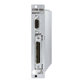
STRAIN/VOLTAGE/ACCELERATION MEASUREMENT CARD
Generally, company names and trade names described in this Instruction Manual are trademarks or registered
trademarks of the companies.
This Instruction Manual may not be copied or reproduced, in whole or part, without consent of KYOWA.
Copyright © KYOWA ELECTRONIC INSTRUMENTS CO., LTD. All rights reserved.
The contents of the Instruction Manual are subjected to change without prior notice.
INSTRUCTION MANUAL
Thank you for purchasing KYOWA's product CVM-40A
Strain/Voltage/Acceleration Measurement Card for EDX-100A
Universal Recorders/EDX-200A Universal Recorders
/EDX-3000A Memory Recorder/Analyzers.
Read this Instruction Manual carefully in order to make full use of
the high performance capabilities of the product.
Do not use the product in methods other than described in this
Manual.
IM-A-880b November,2012
CVM-40A
For EDX-100A/EDX-200A/EDX-3000 A
Advertisement
Table of Contents

Subscribe to Our Youtube Channel
Related Manuals for KYOWA CVM-40A


Summary of Contents for KYOWA CVM-40A
- Page 1 Generally, company names and trade names described in this Instruction Manual are trademarks or registered trademarks of the companies. This Instruction Manual may not be copied or reproduced, in whole or part, without consent of KYOWA. Copyright © KYOWA ELECTRONIC INSTRUMENTS CO., LTD. All rights reserved.
-
Page 2: Table Of Contents
PRIOR TO USE ......................2 SAFETY SYMBOLS ....................2 LIMITED LIFE PARTS AND PREVENTIVE MAINTENANCE ............ 3 CVM-40A REPLACEMENT BEFORE THE END OF SERVICE LIFE ..........3 NOTATIONS USED IN THE INSTRUCTION MANUAL ............3 INFORMATIONAL NOTES ................... 3 1. OUTLINE OF THE PRODUCT ..................4 1.1 Outline of CVM-40A .................... -
Page 3: Standard Accessories
STANDARD ACCESSORIES The following accessories are packed with the CVM-40A Strain/Voltage/Acceleration Measurement Card (hereinafter referred to as the CVM-40A). When unpacking, check the contents to ensure that all accessories are enclosed. Warranty and Test Data Sheet 1 each Cross-recessed binding head machine screw M3 × 6... -
Page 4: Prior To Use
● Lay input cables at proper intervals with a certain play so that they may not receive any unreasonable force. Failure to do so will pose the risk of erroneous data, disconnection and connector failure. ● Do not disassemble or remodel the CVM-40A. Failure to do so will pose the risk of electric shock and system failure. -
Page 5: Limited Life Parts And Preventive Maintenance
Preventive maintenance and replacement parts are a cost-effective way of keeping the performance and extending the service life of the CVM-40A. Regardless of the replacement parts, the CVM-40A itself gradually deteriorates with age. Before the expected service life is reached, consider replacing the CVM-40A with a new one or the latest series as preventive maintenance. -
Page 6: Outline Of The Product
1. OUTLINE OF THE PRODUCT 1.1 Outline of CVM-40A ・ The CVM-40A is a conditioner card for a strain gage, strain gage transducer, voltage, and voltage-output-type piezoelectric accelerometer. The CVM-40A has to be installed in the EDX-100A/200A/3000A. ・ Capable of 8-channel measurement with 1 CVM-40A. -
Page 7: Pin Assignment And Connection Of Input Connector
1.3 Pin Assignment and Connection of Input Connector 1) Input connector [Pin assignment] Pin No.25 Pin No.50 Pin No.1 Pin No.26 Pin No. Connection Pin No. Connection CH1 A CH1 C CH1 F CH1 E,G CH1 B CH1 D CH2 A CH2 C CH2 F CH2 E,G... - Page 8 [Connection Method] CVM input cable: U121 to U-123 (optional) Input connector Plug case (2) Release button (1) Screw To connect, hold the plug case, push it into the input connector to be locked. Then, fasten the plug case tightly with the two screws (1). To disconnect, unfasten the two screws (1).
- Page 9 2) Monitor output connector [Pin assignment] Pin No. Signal Name Pin No. 1 Pin No.6 CH1 monitor output CH2 monitor output CH3 monitor output CH4 monitor output Pin No.5 Pin No.9 CH5 monitor output CH6 monitor output CH7 monitor output CH8 monitor output [Connection Method] Centralized output cable: U-62 (optional)
-
Page 10: Installation Of Cvm-40A
Always turn OFF the EDX-100A/200A/3000A before installing/removing the CVM-40A. Or, damage on the CVM-40A or EDX-100A/200A/3000A may result in. When installing or removing the CVM-40A in/from the EDX-100A/EDX-200A/EDX-3000A, do not touch any component parts of the CVM-40A. Or, system failure or damage may result in. -
Page 11: Connecting Sensors
2. CONNECTING SENSORS The CVM-40A is a conditioner card for a strain gage, strain gage transducer, voltage, and voltage-output-type piezoelectric accelerometer. The input cable should be connected as described below. 2.1 When Using a Strain Gage or Strain Gage Transducer When measuring the output of the strain gage, connect the bridge box to the CVM input cable U-121 to U-123 (optional) as shown in the following figure. -
Page 12: When Applying An Input Voltage
WARNING Do not apply any voltage beyond the specified input voltage range. The specified input voltage range of the CVM-40A is ±50 V. Failure to do so will pose the risk of electric shock, deteriorated performance and system failure. Precautions when measuring the DC voltage of a battery, power supply, etc. -
Page 13: When Using A Voltage-Output-Type Piezoelectric Accelerometer
(optional) to a CVM input cable U-121 to U-123 (optional) as shown in the following figure. NOTE Applicable sensor for the CVM-40A is a voltage-output-type piezoelectric accelerometer. No measurement is allowed if an electric charge output type piezoelectric accelerometer is directly connected. - Page 14 Although the time required until the output voltage becomes stable varies according to sensors in use or CVM-40A measuring range, the output voltage becomes stable in approximately 20 to 40 seconds. Wait for a while until it becomes stable before starting the measurement.
-
Page 15: Setting Channel Conditions
3 SETTING CHANNEL CONDITIONS For the EDX-100A/200A, use the DCS-100A in your PC for settings. For the EDX-3000A, use the EDX-3000A itself or DCS-100A in your PC for settings. For details, refer to "DCS-100A Instruction Manual for EDX-100A/200A/3000A" and "EDX-3000A Instruction Manual for Hardware."... -
Page 16: Details Of Channel Conditions
・ When the input signal is larger than the preset measuring range, both recording data and monitor output signal become saturated. ・ The smaller the measuring range is, the higher becomes the gain of the CVM-40A. Therefore, the noise tends to become larger. - Page 17 4) High Pass Filter Select the high pass filter ON (AC coupling)/OFF (DC coupling) for each channel. For the strain measurement and voltage measurement. : High Pass Filter OFF 0.2 Hz : High Pass Filter ON with the cutoff frequency 0.2 Hz 1 Hz : High Pass Filter ON with the cutoff frequency 1 Hz 5) Low Pass Filter...
- Page 18 7) CAL Select the CAL ON/OFF for each channel. ON : Allowed for outputting the CAL value. When conducting the CAL, the CAL value pre-set in the CAL range is output. OFF : Not allowed for outputting the CAL value. 8) CAL Range ・...
-
Page 19: Specifications
4. SPECIFICATIONS 4.1 Hardware Specifications Item Strain measurement Voltage measurement Acceleration measurement Number of measuring channels Measuring Items Strain gage Voltage Voltage-output-type Strain Gage Transducer Piezoelectric accelerometer (with built-in amplifier) Input Form Balance differential input Balance differential input Unbalance differential 3... - Page 20 *6 AUTO: Low-Pass Filter ON with the cutoff frequency set to 1/4 of the sampling frequency. Resulting to turn ON the antialiasing filter function. *7 When the CVM-40A is installed into the EDX-200A/3000A. (When the CVM-40A is installed into the EDX-100A, the resolution is 16 bits.)
-
Page 21: Outside Drawings
4.2. Outside Drawings - 19 -... -
Page 22: Optional Accessories
5 OPTIONAL ACCESSORIES CVM input cable: U-121, U-122, U-123 The input connector is connected. For how to connect the centralized input cable, see “1-3 PIN ASSIGNMENT AND CONNECTION OF CONNECTORS.” U-121…Cable length: Approx. 0.5 m U-122…Cable length: Approx. 1.0 m U-123…Cable length: Approx. - Page 23 Cable length: Approx. 1.0 m CVM concentrated input cable: N-118 For connecting the voltage input box VI-8A, small-sized bridge box for 1-gage system DBS-120A-8/-350A-8, or one-touch lock type bridge box DB-120V-8/-350V-8 into the CVM-40A. Cable length: Approx. 1.5 m Voltage Input Box: VI-8A Capable of gathering signals from 8 BNC connectors into one for measuring voltage and voltage-output-type piezoelectric accelerometers.
- Page 24 Small-sized bridge box for 1-gage system: DBS-120A-8, DBS-350A-8 Small-sized 8-channel bridge box for strain measurements For the 1-gage 2-wire system and 1-gage 3-wire system. DBS-120A-8…For the gage resistance of 120 ohm DBS-120A-8T…For the gage resistance of 120 ohm with the mounting board DBS-350A-8…For the gage resistance of 350 ohm DBS-350A-8T…For the gage resistance of 350 ohm with the mounting board DBS-120A-8/350A-8...
-
Page 25: Appendix
When inputting the same strain signal or the same voltage signal into the CVM-40A and CDV-40B/A at the same time, time lag occurs between the data of the CVM-40A and that of the CDV-40B/A. Time lag occurs due to the difference of the frequency response, low-pass filter circuit, and A/D converter included in every conditioner card. - Page 26 (2) For the Acc. mode Table 6-2 The low-pass filter and time lag between the CVM-40A and CCA-40A (-F) Low-pass filter of the Frequency response Time lag of the CVM-40A Sampling Frequency CVM-40A, CCA-40A of the CVM-40A [ sec] (Hz)
Need help?
Do you have a question about the CVM-40A and is the answer not in the manual?
Questions and answers