Advertisement
Quick Links
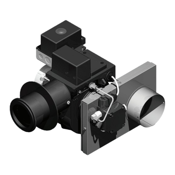
Model 97406 air intake
assembly installed on a
Carlin EZ-1 oil burner
Connecting an outside air supply directly to the burner,
using the Carlin air intake system, requires the follow-
ing:
• Use only a Carlin 97406 for an EZ-1 oil burner, 97406C for
an EZ-LF oil burner, or a 97406A (horizontal) or 97406B
(vertical) air boot for an EZ-Gas burner.
• Obtain and install only a Field Controls Model CAS-1, with
4" inlet air hood and 4" vacuum relief valve.
• The burner and all components must be installed by a
qualified service technician.
• The burner must be started and set up (using combustion
test instruments) according to the burner and appliance
manuals and this air intake system manual.
• Because inlet air temperature affects how much air enters
the burner, the installer must use the combustion set-up
table in this manual to compensate for the air temperature
at the time of combustion adjustment.
Instruction manual
Applies to air intake assemblies:
97406 on EZ-1 burners
97406C on EZ-LF burners
97406A or 97406B on EZ-Gas burners
Installation also requires a Field Controls
Model CAS-1 air hood and vacuum relief
valve, supplied by installer.
Installer/servicer — Except where specifi-
cally stated otherwise, this manual must be used only
by a qualified service technician. (In the state of Mas-
sachusetts, this product must be installed by a licensed
Plumber or Gas Fitter.) Failure to comply with this or
other requirements in this manual could result in severe
personal injury, death or substantial property damage.
Code compliance — Follow all applicable
state and local codes regarding installation of the burner,
appliance, venting and air supply.
©
Copyright 2007 — Carlin Combustion Technology, Inc.
Carlin Combustion Technology, Inc.
70 Maple Street
Ph 413-525-7700
T
800-989-2275
ech support
East Longmeadow, MA 01028
Fx 413-525-8306
carlincombustion.com
Advertisement

Related Manuals for Carlin 97406


Summary of Contents for Carlin 97406
- Page 1 Plumber or Gas Fitter.) Failure to comply with this or • Use only a Carlin 97406 for an EZ-1 oil burner, 97406C for other requirements in this manual could result in severe an EZ-LF oil burner, or a 97406A (horizontal) or 97406B personal injury, death or substantial property damage.
- Page 2 Assemble air intake assembly to the burner (EZ-1 or EZ-LF oil burner) Assemby of 97406 to an EZ-1 or 97406C to an EZ-LF burner Disconnect oil lines as shown above. For burners with integral oil valve fuel units, just disconnect the oil line fitting at the knurled nut as shown.
- Page 3 Model 97406 Combustion air intake system — Instruction manual Where appliance instructions differ from this manual, follow the appliance instructions. Figure 1 Assembling an air intake assembly to a Carlin EZ-1 or EZ-LF oil burner – 3 – Carlin part number 97462 Rev. 09/20/2007...
- Page 4 Model 97406 Combustion air intake system — Instruction manual Where appliance instructions differ from this manual, follow the appliance instructions. Assemble air intake assembly to the burner (EZ-Gas gas burner) Assemby of 97406A or B to an EZ-Gas burner Remove the two bolts that secure the airflow switch bracket to the burner housing. Move the airflow switch out of the way.
- Page 5 Model 97406 Combustion air intake system — Instruction manual Where appliance instructions differ from this manual, follow the appliance instructions. Figure 2 Assembling a 97406A or B air intake assembly to a Carlin EZ-Gas gas burner – 5 – Carlin part number 97462 Rev. 09/20/2007...
-
Page 6: Component Installation
Model 97406 Combustion air intake system — Instruction manual Where appliance instructions differ from this manual, follow the appliance instructions. Install combustion air piping Air piping components Figure 3 Air piping components Field CAS-1 combustion air system The installer must obtain a Field Controls Model CAS-1 inlet air system. The vent piping must include the vacuum relief valve (4”VRV) and intake air hood... -
Page 7: Adjust The Burner Using Test Instruments
Min at setup instruments temperature Propane gas during setup min CO After installing the Carlin air intake system and air piping, you must adjust the burner air settings as directed below. -20 °F to 0 °F 7.5 % 9.4 % 8.7 % 5.8 %... - Page 8 Model 97406 Combustion air intake system — Instruction manual Where appliance instructions differ from this manual, follow the appliance instructions. – 8 – Carlin part number 97462 Rev. 09/20/2007...
Need help?
Do you have a question about the 97406 and is the answer not in the manual?
Questions and answers