Advertisement
Table of Contents
- 1 Table of Contents
- 2 PLEASE Read this First
- 3 Codes and Standards
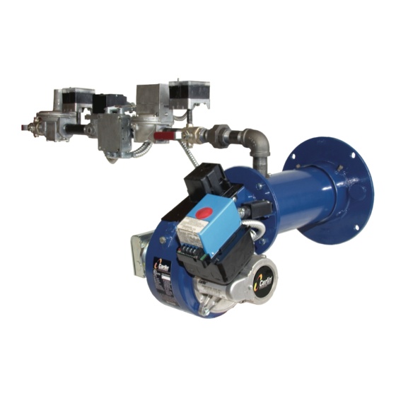
- 4 301GAS Burner At-A-Glance
- 5 Prepare Site • Prepare Burner • Mount Burner
- 6 Install Gas Piping
- 7 Wire Burner
- 8 Check System • Start-Up Burner/Appliance
- 9 Perform Checkout Procedures • Fill out Certificate
- 10 Maintenance and Service Procedures
- 11 Troubleshooting
- 12 Dimensions and Mounting Information
- 13 Replacement Parts
- Download this manual
Ratings
.............................................401,000 to 1,100,000 Btuh
Input:
........................................... Natural gas or propane gas
Fuels:
Max. supply pressure .............................. 14 inches w.c.
Min. supply pressure ................................. 5 inches w.c.
Manifold pressure ................................... 3.5 inches w.c.
Power ............................................120V/60 Hz/1-Phase
Electrical:
Motor ................................1/6 HP, 3450 RPM, 1.8 amps
Total Current .......................................Approx. 2.5 amps
............................Carlin Model 41800 solid state ignitor
Ignition:
..............Carlin Model 60200FR microprocessor control
Control:
........................................................................UL Listed
Agencies:
Installer/servicer - Except where specifically stated other-
wise, this manual must be used only by a qualified service
technician. (In the state of Massachusetts, this product must
be installed by a licensed Plumber or Gas Fitter.) Failure to
comply with this or other requirements in this manual could
result in severe personal injury, death or substantial property
damage.
User - Refer only to User's Information booklet for
information regarding operation of this burner. The burner
Instruction Manual is intended only for your service techni-
cian. The burner and heat exchanger must be inspected and
started at least annually by your service technician.
Instruction Manual
Contents
PLEASE read this first ...........................................................2
Codes and standards ............................................................2
301GAS burner at-a-glance ...................................................3
Prepare site • prepare burner • mount burner .....................4
Install gas piping ..................................................................10
Wire burner ..........................................................................11
Check system • start-up burner/appliance .........................12
Perform checkout procedures • fill out certificate ..............14
Maintenance and service procedures ..................................16
Troubleshooting ...................................................................17
Dimensions and mounting information ................................19
Replacement parts ..............................................................20
©
Copyright 2014 - Carlin Combustion Technology, Inc.
Carlin Combustion Technology, Inc.
126 Bailey Road
Ph 203-680-9401
T
800-989-2275
ech support
™
North Haven, CT 06473
Fx 203-680-9403
carlincombustion.com
Advertisement
Table of Contents

Related Manuals for Carlin 301GAS


Summary of Contents for Carlin 301GAS
-
Page 1: Table Of Contents
© Copyright 2014 — Carlin Combustion Technology, Inc. User — Refer only to User’s Information booklet for Carlin Combustion Technology, Inc. information regarding operation of this burner. The burner... -
Page 2: Please Read This First
National Fuel Gas Code, ANSI Z223.1/ Burner listings NFPA 54-latest edition, and the National Electrical code, ANSI/NFPA 70-lat- Carlin 301GAS burners are tested and approved under standards UL795 est edition for U. S. installations or B149.1/B149.2 Installation Code, and and CGA 3.4-latest edition. -
Page 3: 301Gas Burner At-A-Glance
Automatic gas valve gas manifold assembly Junction box with terminal strip 22 Ignitor (Carlin Model 41800 solid state electronic ignitor — 9,000 volts, Automatic gas valve (diaphragm type) continuous duty rated) Diaphragm gas valve bleed port (can be fitted with fixed bleed orifice) –... -
Page 4: Prepare Site • Prepare Burner • Mount Burner
Model 301GAS burner — Instruction manual Where appliance instructions differ from this manual, follow the appliance instructions. 1. Prepare site • prepare burner • mount burner Vent system Figure 1 Vent and vent connector installations, typical Inspect, repair and/or replace vent system... - Page 5 Model 301GAS burner — Instruction manual Where appliance instructions differ from this manual, follow the appliance instructions. 1. Prepare site • prepare burner • mount burner (continued) Combustion air/ventilation openings Sizing air openings Follow all applicable codes and the appliance instruction manual (when General available) to size combustion air openings.
- Page 6 Model 301GAS burner — Instruction manual Where appliance instructions differ from this manual, follow the appliance instructions. 1. Prepare site • prepare burner • mount burner (continued) Prepare the appliance Clean the appliance: Clean the appliance thoroughly and seal all joints. Test all electrical components and verify the relief valve works (boilers only).
- Page 7 Combustion head/air tube configurations • 301GAS burners are supplied with either an “B” or “C” head and air tube combination. The “B” head/tube is designed for the low range from 401 to 700 MBH. The “C” head/tube is for the high range from 550 MBH to 1,100 MBH.
- Page 8 Model 301GAS burner — Instruction manual Where appliance instructions differ from this manual, follow the appliance instructions. 1. Prepare site • prepare burner • mount burner (continued) Inspect/correct flame rod/electrode Figure 5 Combustion head • Before installing the burner in the appliance, inspect the flame rod and electrode.
- Page 9 Model 301GAS burner — Instruction manual Where appliance instructions differ from this manual, follow the appliance instructions. 1. Prepare site • prepare burner • mount burner (continued) Mount burner in appliance Install gas train on burner • Verify appliance burner front plate dimensions and bolt locations.
-
Page 10: Install Gas Piping
Model 301GAS burner — Instruction manual Where appliance instructions differ from this manual, follow the appliance instructions. 2. Install gas piping from meter to combination gas train Code compliance Table 2 Capacities of black iron pipe, cubic feet gas/hour The burner/appliance installation must comply with codes listed on page 2 NATURAL GAS and any other locally applicable codes. -
Page 11: Wire Burner
1. The burner requires a 120 /single-phase power supply, with at least a 10- on page 2 and any other locally applicable codes. amp fuse. The current draw will be (when equipped with typical motor and Carlin 41800 electronic ignitor) approximately: General wiring requirements Read and follow the guidelines below. -
Page 12: Check System • Start-Up Burner/Appliance
Model 301GAS burner — Instruction manual Where appliance instructions differ from this manual, follow the appliance instructions. 4. Check system • start-up burner/appliance Inspect/check system Figure 12 Air band adjustment Before starting the burner and appliance, verify the system has been installed as directed by this manual and the appliance instructions. - Page 13 Model 301GAS burner — Instruction manual Where appliance instructions differ from this manual, follow the appliance instructions. 4. Check system • start-up burner/appliance (continued) Should overheating or an emergency occur, immediately: Model 60200FR diagnostic LED’s • Shut off main manual gas valve.
-
Page 14: Perform Checkout Procedures • Fill Out Certificate
Model 301GAS burner — Instruction manual Where appliance instructions differ from this manual, follow the appliance instructions. 5. Perform checkout procedures • fill out certificate Installer/servicer Make final burner adjustments (continued) Please check off and fill in certificate Inspect flame ❏... - Page 15 Model 301GAS burner — Instruction manual Where appliance instructions differ from this manual, follow the appliance instructions. 5. Perform checkout procedures • fill out certificate (continued) Verify burner/appliance operation Check burner/appliance/controls operation ❏ ❏ Test operating and limit controls on appliance as specified in appliance Check flange door switch instruction manual.
-
Page 16: Maintenance And Service Procedures
Model 301GAS burner — Instruction manual Where appliance instructions differ from this manual, follow the appliance instructions. 6. Maintenance and service procedures Annual start-up & service Maintenance/service procedures Cleaning blower wheel This burner should be started and serviced at least annually by a qualified service technician. -
Page 17: Troubleshooting
Model 301GAS burner — Instruction manual Where appliance instructions differ from this manual, follow the appliance instructions. 7. Troubleshooting – 17 – Carlin part number MN301GAS Rev. 11/24/14... - Page 18 Model 301GAS burner — Instruction manual Where appliance instructions differ from this manual, follow the appliance instructions. 7. Troubleshooting (continued) Problem Possible Corrective action cause These procedures must only be performed by a qualified service techni- cian. Use care when performing tests on electrically or mechanically live WARNING parts.
-
Page 19: Dimensions And Mounting Information
Model 301GAS burner — Instruction manual Where appliance instructions differ from this manual, follow the appliance instructions. 8. Dimension and mounting information Figure 13 Dimensional data Carlin 60200 primary Cast aluminum housing 11 Secondary gas valve Air tube Air flow switch... -
Page 20: Replacement Parts
Ignitor, Carlin electronic Model 41800 4180002C Burner junction box, 4" x 4", with grommet, lock washer, conduit nipples (to burner housing) 99198KIT Primary control, Carlin 60200FR microprocessor flame rod control 602002FR943S Optional adjustable forced draft flange 99255 – 20 –... - Page 21 Model 301GAS burner — Instruction manual Where appliance instructions differ from this manual, follow the appliance instructions. 9. Replacement parts – Burner (continued) Set screws Burner is shown with welded flange, supplied only on burners ordered for specific appliance applications. Other burners are supplied with the optional forced draft adjustable flange (item 18).
- Page 22 Model 301GAS burner — Instruction manual Where appliance instructions differ from this manual, follow the appliance instructions. 9. Replacement parts – Gas train Item Description Part number number Pipe plug, 1/4” NPT (3 required) Obtain locally Gas cock, 1” NPT 99225 Pipe nipple, schedule 40 steel, 1”...
- Page 23 Model 301GAS burner — Instruction manual Where appliance instructions differ from this manual, follow the appliance instructions. 9. Replacement parts – Gas train (continued) – 23 – Carlin part number MN301GAS Rev. 11/24/14...
- Page 24 Model 301GAS burner — Instruction manual Where appliance instructions differ from this manual, follow the appliance instructions. – 24 – Carlin part number MN301GAS Rev. 11/24/14...
Need help?
Do you have a question about the 301GAS and is the answer not in the manual?
Questions and answers