Carlin 201CRD Instruction Manual
Hide thumbs
Also See for 201CRD:
- Instruction manual (89 pages) ,
- Instruction manual (28 pages) ,
- Installation and operating instructions manual (8 pages)
Table of Contents
Advertisement
Quick Links
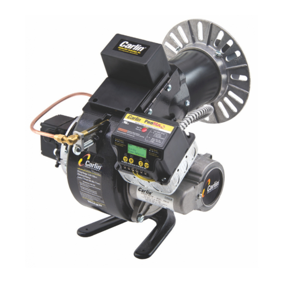
MODELS
201CRD &
301CRD
Advanced Commercial Burners
2.5 to 5.5 GPH & 3.0 to 7.0 GPH
Instruction Manual
Installer/servicer — Except where specifically
stated otherwise, this manual must be used
only by a qualified service technician. Failure
to comply with this or other requirements in this
manual could result in severe personal injury,
death or substantial property damage.
User — The burner Instruction Manual is in-
tended only for your service technician. The
burner and heat exchanger must be inspected
and started at least annually by your service
technician.
The National Oilheat Research Alliance (NORA)
recommends single pipe oil systems and high-
quality filtration for all fuel types. This should in-
clude at least a 10 micron Spin-on filter. Double
filtration provides even greater assurance clean
fuel will get to the pump. Contaminants in the
tank that enter the fuel supply to the burner
can cause pump sticking/seizing. These con-
taminants may increase in the early stages of
transitioning to modern fuels (Ultra Low Sulfur
and Bio Blends). High quality filtration adds
protection against pump sticking.
Ratings
Input:
201CRD ............................................ 2.50 to 5.00 GPH
301CRD (3¼" air cone) ..................... 3.00 to 6.00 GPH
301CRD (3½" air cone) ..................... 4.00 to 7.00 GPH
Fuels:
U.S. ............... No. 1 or No. 2 Fuel oil ncluding Bio Blends
Canada ...................... No. 1 Stove oil or No. 2 Heating oil
Fuel unit:
................................. Suntec A2YA-7916 or B2YA-8916
...................................................Factory set at 150
Electrical:
Power ........................................... 120V/60 Hz/1-Phase
Motor ..............................Carlin PSC, 1/4 HP, 3450 RPM
Total current at 120V/60 Hz/1-Phase:
201CRD .................................. Approx. 3.2 amps
301CRD .................................. Approx. 3.2 amps
Ignition:
................ Carlin Model 45000 electronic – 19,000 volts
Control:
.............................................U.L. primary safety control
Agencies:
............................................ UL Listed (US and Canada)
126 Bailey Road • North Haven, CT 06473
Phone 203-680-9401 • Fax 203-764-1714
T
800-989-2275 • carlincombustion.com
ech support
© Copyright 2021 — Carlin Combustion Technology
not exceeding B20 (U.S ONLY)
psig
Advertisement
Table of Contents

Related Manuals for Carlin 201CRD


Summary of Contents for Carlin 201CRD
- Page 1 Total current at 120V/60 Hz/1-Phase: 201CRD ........Approx. 3.2 amps 301CRD ........Approx. 3.2 amps Ignition: ....Carlin Model 45000 electronic – 19,000 volts Installer/servicer — Except where specifically stated otherwise, this manual must be used Control: ..........U.L. primary safety control only by a qualified service technician. Failure...
-
Page 2: Table Of Contents
Model 201CRD & 301CRD Advanced Oil Burners — Instruction Manual PLEASE read this first . . . Contents Before installing or servicing . . . PLEASE read this first .............2 General information ..............3 Codes and standards ..............3 Should overheating occur: (1) Shut off the oil supply to the burner. -
Page 3: General Information
Codes and standards Certification 201CRD and 301CRD burners are U.L. listed for the U.S. and Canada, certified to comply with ANSI/UL 296, for use with #1 or #2 heating oil as well as bio blends not exceeding B20 (U.S. Only) (per standard ASTM D396). -
Page 4: Prepare Site • Assemble Burner • Mount Burner
Model 201CRD & 301CRD Advanced Oil Burners — Instruction Manual 2. Prepare site • assemble burner • mount burner Vent system Residential installation air openings Residential — Unconfined spaces (at least 7,000 cubic feet per GPH) General • An unconfined space means a room with at least 7,000 cubic feet volume for each GPH input (or 50 cubic feet per MBH) of all appliances in the room. - Page 5 Model 201CRD & 301CRD Advanced Oil Burners — Instruction Manual 2. Prepare site • assemble burner • mount burner (continued) Combustion/ventilation air checklist Table 2 Minimum combustion/ventilation air openings The burner may operate successfully under momentary downdraft conditions, but sustained downdraft is unsafe.
- Page 6 Model 201CRD & 301CRD Advanced Oil Burners — Instruction Manual 2. Prepare site • assemble burner • mount burner (continued) Verify combustion chamber Figure 1 Combustion chamber configurations, typical Chamber dimensions and construction • If retrofitting the burner to an appliance, install the burner in accordance with the appliance instruction manual, when available.
- Page 7 Model 201CRD & 301CRD Advanced Oil Burners — Instruction Manual 2. Prepare site • assemble burner • mount burner (continued) Table 3 201CRD and 301CRD Minimum combustion chamber dimensions (all dimensions in inches) - See Figure 1 for combustion chamber configurations – 7 – MN2301 032501...
- Page 8 Model 201CRD & 301CRD Advanced Oil Burners — Instruction Manual 2. Prepare site • assemble burner • mount burner (continued) Inspect burner and components Figure 2 Standard adjustable flange (universal flange) General • Check the air tube length. Verify the usable length of the tube UTL will be long enough (see “Mount burner in appliance”).
- Page 9 Model 201CRD & 301CRD Advanced Oil Burners — Instruction Manual 2. Prepare site • assemble burner • mount burner (continued) Mount burner in appliance Pedestal-mounted burners 1. Check the diameter of the appliance opening. If larger than 4½ inches, Welded flange-mounted burner rebuild the opening so the open is reduced to 4½...
-
Page 10: Prepare Burner
Model 201CRD & 301CRD Advanced Oil Burners — Instruction Manual 3. Prepare burner Removing/installing head assembly Figure 7 Removing/inserting combustion head assembly Use care when handling burner components after the burner has been firing. Components can be hot and could cause severe personal injury. - Page 11 Model 201CRD & 301CRD Advanced Oil Burners — Instruction Manual 3. Prepare burner (continued) Install nozzle/check electrodes Figure 9 Replacing the oil nozzle — 1. Loosen the clamp screw on the retention ring assembly (see Figure 9, 1 – Remove retention ring from nozzle adapter step 1).
- Page 12 Model 201CRD & 301CRD Advanced Oil Burners — Instruction Manual 3. Prepare burner (continued) Set initial burner air settings Figure 12 Air band setting Combustion head (“A” dimension) 1. The combustion head adjusting screw is used to set the spacing between the retention ring and throttle ring (or air cone), regulating how much air passes around the retention ring.
- Page 13 Model 201CRD & 301CRD Advanced Oil Burners — Instruction Manual 3. Prepare burner (continued) • Check all connections and joints to ensure they are air-tight. Table 4 Approximate air band and combustion head settings • Use flare fittings. DO NOT use compression fittings.
- Page 14 Model 201CRD & 301CRD Advanced Oil Burners — Instruction Manual 3. Prepare burner (continued) One-line fuel system requirements Figure 15 Two-line fuel system • See Figure 14. • The standard burner fuel unit is a single-stage, 3450-RPM oil pump. Apply this fuel unit only on one-line systems where the fuel supply is on the same level with, or higher than, the burner.
- Page 15 Oil flow schematics / fuel unit connections Verify before starting burner: • Figures 16 and 17 show oil flow for Carlin 201 and 301 burners and show Should overheating or an emergency occur, immediately: port functions for Suntec Model A and B pumps.
-
Page 16: Adjustment And Verification
Model 201CRD & 301CRD Advanced Oil Burners — Instruction Manual 4. Adjustment and verification Adjust burner using test instruments Firing against positive overfire pressure 1. Operate burner for 15 minutes before making final adjustments using test equipment. 2. Check for leaks in fuel piping. -
Page 17: Annual Start-Up And Service
Model 201CRD & 301CRD Advanced Oil Burners — Instruction Manual 4. Adjustment and verification 5. Annual start-up and service (cont.) Verify burner/appliance operation Annual start-up & service This burner must be started and serviced at least annually Check burner / appliance / controls by a qualified service technician. -
Page 18: Repair Parts
Model 201CRD & 301CRD Advanced Oil Burners — Instruction Manual 6. Repair parts For parts not shown or listed, contact factory and/or check separate documentation supplied with appliance/burner unit. ITEM PART NO. DESCRIPTION ITEM PART NO. DESCRIPTION 54155S 7" Nominal, 16-3/4" OAL Combustion Head Assy •... - Page 19 Model 201CRD & 301CRD Advanced Oil Burners — Instruction Manual 6. Repair parts (cont.inued) † † † † *3 includes selected air tube and combustion head assembly † 18 includes multiple parts NOTE: Parts may not be exactly as shown in diagram.
-
Page 20: Maintenance/Service Procedures
Model 201CRD & 301CRD Advanced Oil Burners — Instruction Manual 7. Maintenance/service procedures Checking ignitor Turn off power to appliance when servicing burner. Failure to comply could result in severe personal injury, death or substantial property Never test an ignitor by placing a screwdriver (or other metallic damage. -
Page 21: Warranty
Model 201CRD & 301CRD Advanced Oil Burners — Instruction Manual For New Warranty Information, Visit carlincombustion.com/warranty – 21 – MN2301 032501... -
Page 22: User Care And Maintenance
Model 201CRD & 301CRD Advanced Oil Burners — Instruction Manual 201CRD & 301CRD Burner User care and maintenance Refer only to the information on this page, intended for your use. The remainder of this manual is intended only for your service technician.
Need help?
Do you have a question about the 201CRD and is the answer not in the manual?
Questions and answers