Advertisement
Quick Links
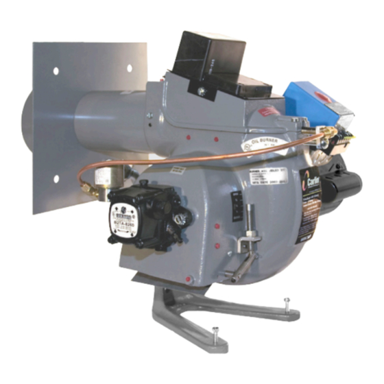
"CRD" burners feature a combustion head
incorporating a new design concept which
provides a means to control the air pattern
to match the nozzle requirements. The aero-
dynamics for optimum combustion are easily
adjusted for any nozzle size without changing
the air-handling hardware. The flame front is
initiated inside the air tube so that no erratic re-
circulating gasses from the main chamber area
can quench the flame at the retention ring.
The letters "CRD" stand for "Controlled
Retention-Double Speed."
Use of a small blower wheel (fan) operating
at 3450 rpm provides a more positive, yet quiet,
air flow which does not yield to normal draft
variations and therefore assures a more con-
stant air-fuel ratio for dependably clean com-
bustion day after day.
©
Copyright 2018 — Carlin Combustion Technology, Inc.
Model 601CRD
Oil Burner
Installation and
Operating Instructions
For Use By Qualified Service Technicians Only
Fuel Specification ................................... ASTM U396 No.2
Firing Range ......................................................6.00-13.20*
Motor HP, rpm .................................................½, 3450 rpm
Motor Phase, Hz ............................................ Single, 60 Hz
Motor Amps .................................................... 8.4 (approx.)
Motor Volts, Standard ................................................ 120V
Motor Volts, Optional .............................................. 230V**
Motor Contactor .......................................DPST-Optional**
Standard Control Type ............................................. 70200
Control Volts, Hz ............................................. 120 V, 60 Hz
Ignitor ....................................................................... 14,000
Burner Housing ......................................... Rugged Casting
Blower Wheel Diam. x Width .............................. 6
2-Stage Fuel Unit Pressure .................................... 150 psi
Oil.Valve Volts, Hz ........................................... 120 V, 60 Hz
Oil Nozzle Specs. ...................................................... 45° ss
Approximate Shipping Weight ................................. 65 lbs
* The maximum high-fire capability shown is for natural draft. With forced draft, the maximum
firing rate is reduced.
** Motor contactor optional for Model 601CRD at an additional cost. Required when motor is
for 230 volts.
Carlin Combustion Te chnology, Inc.
126 Bailey Rd
Ph 203-680-9401
Tech Support 800-989-2275
⁄
1
" X 4"
4
North Haven, CT 06473
Fx 203-680-9403
carlincombustion.com
Advertisement

Related Manuals for Carlin 601CRD


Summary of Contents for Carlin 601CRD
-
Page 1: Operating Instructions
* The maximum high-fire capability shown is for natural draft. With forced draft, the maximum firing rate is reduced. ** Motor contactor optional for Model 601CRD at an additional cost. Required when motor is for 230 volts. Carlin Combustion Te chnology, Inc. - Page 2 2. Slide the end of the air tube into the opening and secure the flange to the front plate. About Combustion Chambers Installing The Burner: The model 601CRD operates with superior efficiency Pedestal Mounted and cleanliness in properly designed refractory-type combustion chambers. Very wide tolerance to burner 1.
- Page 3 Table 1. Recommended Minimum Dimensions of Combustion Chamber for Model 601CRD (inches) Minimum Inside Dimensions In Refractory Minimum Dimensions In Boilers Fired Type Combustion Chambers (Ins.) Without Refractory Chambers (Ins.) Firing Rate Length (L) Length (L) Dimen- Dimen- Nozzle (GPH) at...
- Page 4 Installing and Wiring The 70200 control must be installed and serviced only by a qualified service technician. Always disconnect power source before wiring to avoid electrical shock or damage to the control. All wiring must comply with applicable codes and ordinances. Mounting The control may be mounted on a 4"...
- Page 5 Each division is 1/16 inch. Fig. 9 Retention Ring and Air Shutter Table 2. Approximate Settings for Model 601CRD ⁄ " x 4" Blower Wheel) Adjustments Nozzle...
- Page 6 GPH capability becomes. Note that the graph at the right stops at 0.30 inches W.C. for Model 601CRD; the maximum recom- mended back pressure for this model. The combustion head settings for forced draft firing would be somewhat greater than those shown in Table 2, page 5, which are for zero pressure or natural draft.
Need help?
Do you have a question about the 601CRD and is the answer not in the manual?
Questions and answers