Carlin 701CRD Installation And Operating Instructions Manual

Carlin 701CRD Installation And Operating Instructions Manual

Oil burners

Advertisement

It is important that the installation of the oil burner,
piping and fittings, safety devices, controls, electrical
wiring and equipment be done in accordance with
national and/or local regulations of the authorities
having jurisdiction over such installation.
©
Copyright 2017 — Carlin Combustion Technology, Inc.
701CRD/801CRD

Operating Instructions

For Use By Qualified Service Technicians Only
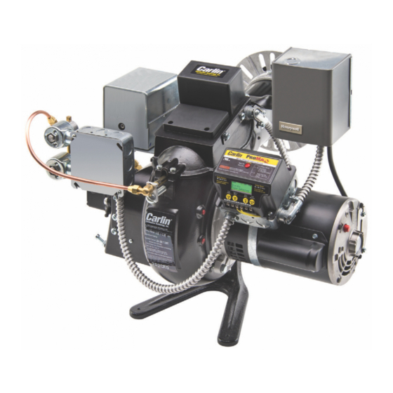
701CRD

DESCRIPTION

"CRD" burners feature a combustion head incorporating a
design concept which provides a means to control the air
pattern to match the nozzle requirements. The aerodynam-
ics for optimum combustion are easily adjusted for any
nozzle size without changing the air-handling hardware.
The flame front is initiated inside the airtube so that no er-
ratic recirculating gases from the main chamber area can
quench the flame at the retention ring.
The letters "CRD" stand for "Controlled Retention–Double
Speed." Carlin Models 70lCRD and 80lCRD, for use with
No. 2 fuel oil, are low-high-low-off (step modulating) high
speed flame retention burners. Oil flow–rate is step-modu-
lated by the use of two oil valves and two nozzles. Com-
bustion air is controlled by a damper motor. It's end-switch
energizes the second stage valve as the air shutter ap-
proaches a wide open position.
801CRD
Due to the low-high-low feature of these burners they are
very versatile and efficient:
1. They can operate in forced draft boilers or furnaces at
pressures up to 0.50 inches W.C.
2. They will save typically. 20% in seasonal fuel consump-
tion compared to conventional single-stage flame reten-
tion burners.
3. They can operate with or without refractory lined com-
bustion chambers.
4. They are superior for process applications.
5. They can be installed through fire door openings.
Carlin Combustion Te chnology, Inc.
126 Bailey Rd
Ph 203-680-9401
Tech Support 800-989-2275
1
Oil Burners
Installation and
North Haven, CT 06473
Fx 203-680-9403
carlincombustion.com

Advertisement

Table of Contents
loading
Need help?

Need help?

Do you have a question about the 701CRD and is the answer not in the manual?

Questions and answers

Subscribe to Our Youtube Channel

Summary of Contents for Carlin 701CRD

  • Page 1: Operating Instructions

    The letters “CRD” stand for “Controlled Retention–Double Speed.” Carlin Models 70lCRD and 80lCRD, for use with No. 2 fuel oil, are low-high-low-off (step modulating) high speed flame retention burners. Oil flow–rate is step-modu- lated by the use of two oil valves and two nozzles.
  • Page 2 5. If, after returning to low fire, the load should drop to head and combustion air. DIMENSIONS STD. FORCED DRAFT MODEL MODEL B.C. B.C. O.D. FLANGE FLANGE 701CRD ⁄ ⁄ ⁄ ⁄ ⁄ ⁄ ⁄ ⁄ 701CRD 59642 ⁄ ⁄...
  • Page 3 CHAMBERS warm-up properties, the light, insulating-type materials are slightly preferable although these burners show less The Models 701CRD and 801CRD operate with superior efficiency dependence upon refractory temperature than previous and cleanliness in properly designed refractory-type combustion models. Refractory materials in boilers and furnaces should chambers.
  • Page 4 Normally a draft of 0.02 to 0.04 inches W.C. (nega- tive pressure) is recommended over the fire for natural draft applications. Model 701CRD is provided with a low fire air shutter ad- justing screw. This adjustment limits the amount of shutter...
  • Page 5 3/8" 6.50 6.50 7.80 15.60 7/16" 1/2" TABLE 8 6.50 7.00 7.80 16.20 1/2" 1/2" MODEL 701CRD & MODEL 801CRD 6.50 7.50 7.80 16.80 3/8" 1/2" TWO-STAGE UNITS–TWO-PIPE SYSTEMS (150 PSI) 6.50 8.00 7.80 17.40 3/4" 1/2" Length of Tubing (feet) 6.50...
  • Page 6 NOT ALTER THE LINKAGE. IT IS PRE-SET AT THE FAC- Refer to the appropriate example for your installation. TORY. Model 701CRD is provided with a low fire air shutter ad- justing screw. This adjusting limits the amount of shutter closure which thereby increases or decreases the amount of combustion air required for proper burning.
  • Page 7 Example: Steam Boiler Operating Range 3 to 6 PS1 2. Set Safety Hi Limit: Cut in 8 PSl / Cut out I0 PSI 3. Set Operating Limit: Cut in 8 PSl / Cut out 6 PSI 4. Set Hi Fire Control: Cut in 3 PSl / Cut out 4 PSI Operation: 1.
  • Page 8 T E C H S U P P O R T H O T L I N E 8 0 0 - 9 8 9 - 2 2 7 5 Carlin Combustion Technology, Inc. 126 Bailey Road North Haven, CT 06473 Phone 203–680–9401 Fax 203–764–1714 info@carlincombustion.com www.carlincombustion.com e-mail us at: visit our website: © Copyright 2015 — Carlin Combustion Technology, Inc. MN0000 050317...

This manual is also suitable for:

801crd

Table of Contents